

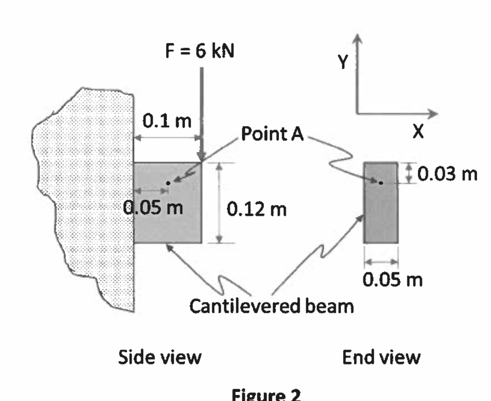
Question: Figure 2 shows a side view and an end view of a cantilevered rectangular beam with dimensions of 0 . 1 m long, 0 .
Figure shows a side view and an end view of a cantilevered rectangular beam with dimensions of m long, m high and m wide. A kN point load is applied to the end of the beam as illustrated.
aCalculate the normal and shear stresses in the X and Y directions at point A
bCalculate the principal stresses at point A
c Calculate the orientation of the principal planes at point A with respect to the X axis
dDetermine which principal stresses act on which principal planes.
eSketch the element at point A clearly showing the orientation of the principal planes and the magnitude and direction of the principal stresses.
f Calculate the maximum and minimum shear stresses at point A
g What are the values of the normal stresses in the planes containing the maximum and minimum shear stresses at point A
Step by Step Solution
There are 3 Steps involved in it
1 Expert Approved Answer
Step: 1 Unlock

Question Has Been Solved by an Expert!
Get step-by-step solutions from verified subject matter experts
Step: 2 Unlock
Step: 3 Unlock