

Question: Figure 3 . 1 5 Floor plan for Problem 3 . 1 9 . 3 . 1 9 Find the design heat loss from a
Figure
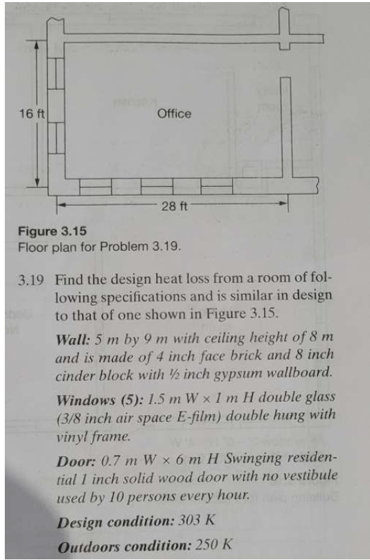
Floor plan for Problem
Find the design heat loss from a room of following specifications and is similar in design to that of one shown in Figure
Wall: m by m with ceiling height of m and is made of inch face brick and inch cinder block with inch gypsum wallboard.
Windows : mathrm~mWtimes mathrmmH double glass inch air space Efilm double hung with vinyl frame.
Door: mathrm~mWtimes mathrmmH Swinging residential inch solid wood door with no vestibule used by persons every hour.
Design condition: K
Outdoors condition: K
Step by Step Solution
There are 3 Steps involved in it
1 Expert Approved Answer
Step: 1 Unlock

Question Has Been Solved by an Expert!
Get step-by-step solutions from verified subject matter experts
Step: 2 Unlock
Step: 3 Unlock