

Question: Figure 3 represents a 4-bit universal shift register (USR-4), and the meaning of the inputs. Figure 3 represents a 4-bit universal shift register (USR-4), and
Figure 3 represents a 4-bit universal shift register (USR-4), and the meaning of the inputs.
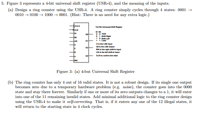
Figure 3 represents a 4-bit universal shift register (USR-4), and the meaning of the inputs. (a) Design a ring counter using the USR-4. A ring counter simply cycles through 4 states: 0001 rightarrow 0010 rightarrow 0100 rightarrow 1000 rightarrow 0001. (b) The ring counter has only 4 out of 16 valid states. It is not a robust design. If its single one output becomes zero due to a temporary hardware problem (e.g. noise), the counter goes into the 0000 state and stay there forever. Similarly if one or more of its zero outputs changes to a 1, it will enter into one of the 11 remaining invalid states. Add minimal additional logic to the ring counter design using the USR-4 to make it self-correcting. That is, if it enters any one of the 12 illegal states, it will return to the starting state in 4 clock cycles
Step by Step Solution
There are 3 Steps involved in it

Get step-by-step solutions from verified subject matter experts