

Question: Figure 4 : Active Filter Circuit Diagram Consider the first order circuit illustrated in 4 . Use whatever computer resource you prefer for the following
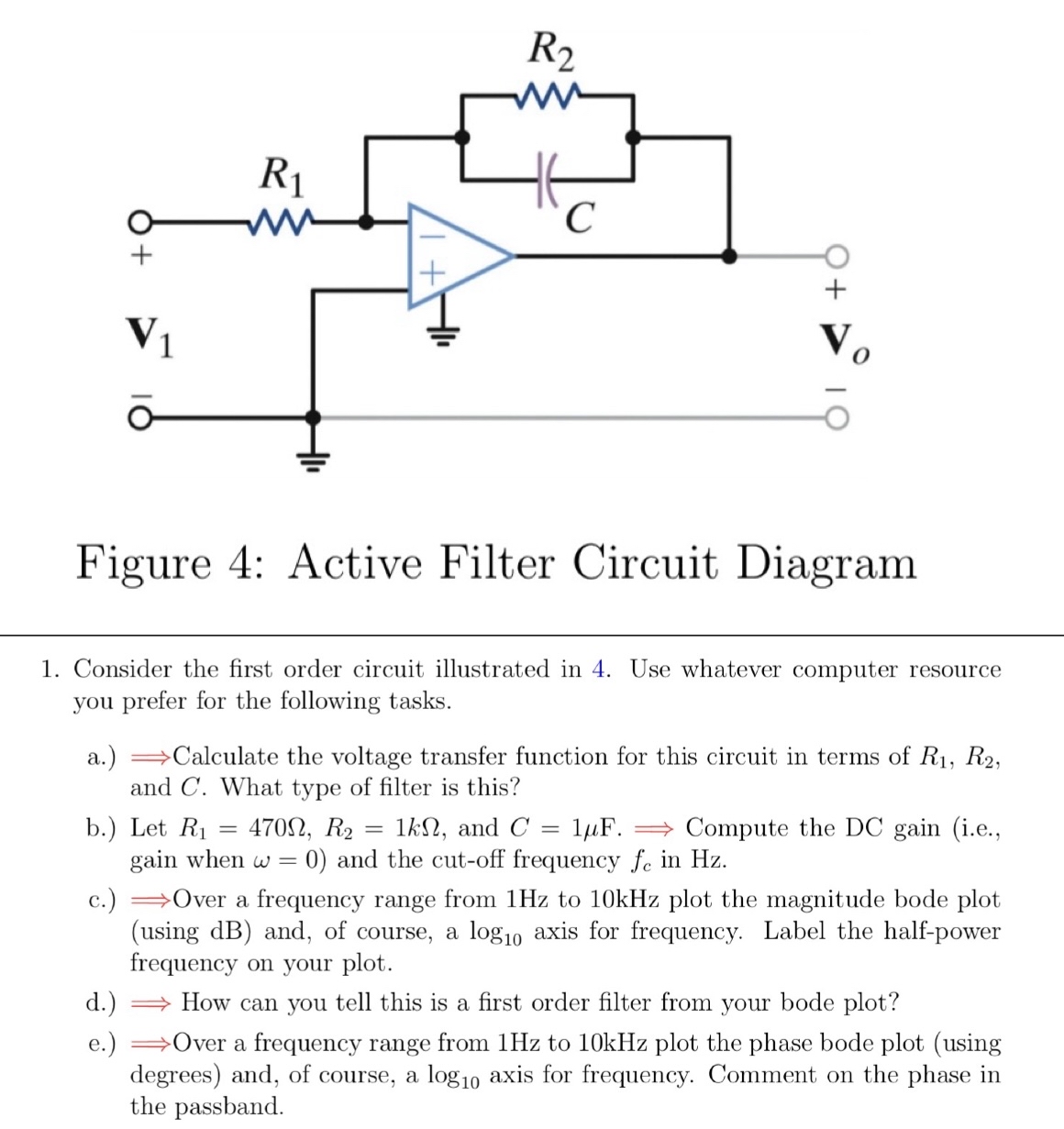
Figure : Active Filter Circuit Diagram
Consider the first order circuit illustrated in Use whatever computer resource you prefer for the following tasks.
a Longrightarrow Calculate the voltage transfer function for this circuit in terms of and What type of filter is this?
b Let and Longrightarrow Compute the DC gain ie gain when and the cutoff frequency in Hz
c Longrightarrow Over a frequency range from Hz to kHz plot the magnitude bode plot using dB and, of course, a axis for frequency. Label the halfpower frequency on your plot.
d Longrightarrow How can you tell this is a first order filter from your bode plot?
e Longrightarrow Over a frequency range from Hz to kHz plot the phase bode plot using degrees and, of course, a axis for frequency. Comment on the phase in the passband.
Step by Step Solution
There are 3 Steps involved in it
1 Expert Approved Answer
Step: 1 Unlock

Question Has Been Solved by an Expert!
Get step-by-step solutions from verified subject matter experts
Step: 2 Unlock
Step: 3 Unlock