

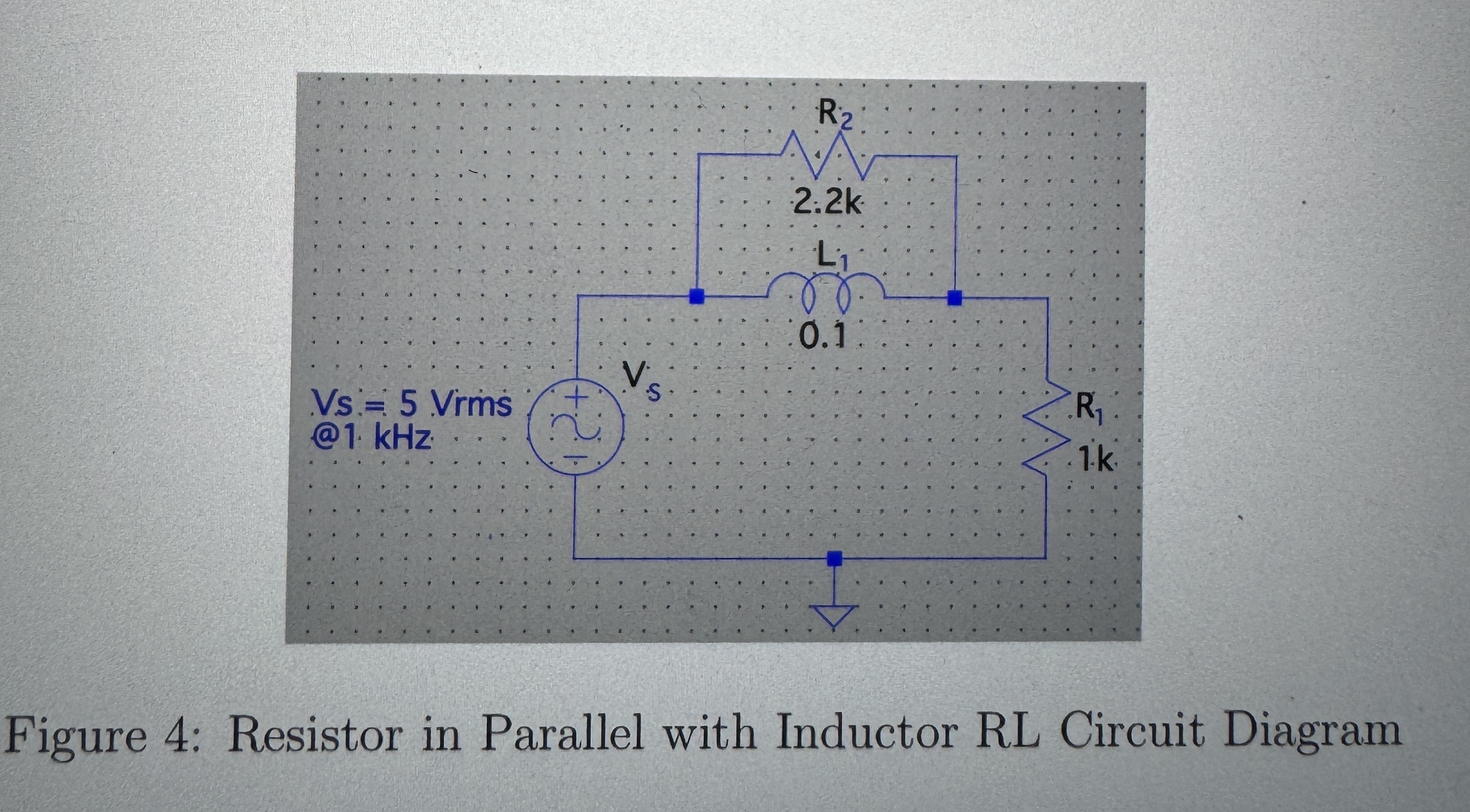
Question: Figure 4 : Resistor in Parallel with Inductor RL Circuit Di For the circuit illustrated in Figure 4 keep V S being a 5 V
Figure : Resistor in Parallel with Inductor RL Circuit Di
For the circuit illustrated in Figure keep being a sinusoid of and while adding resistor in parallel with inductor This introduction of the additional resistance makes the inductor phasor "less ideal." For this circuit the phasor is taken to be the voltage across the inductor in the circuit.
a Longrightarrow Find the magnitude and phase angle of I, and
b Longrightarrow Draw a phasor diagram to scale showing the phasor voltages and Use the voltage across the resistor, as the reference horizontal phasor.
c Switch the positions of resistors and in the circuit. Longrightarrow Draw a phasor diagram to scale showing the phasor voltages and Use the voltage across the resistor, as the reference horizontal phasor.agram
Figure : Resistor in Parallel with Inductor RL Circuit Diagram
Step by Step Solution
There are 3 Steps involved in it
1 Expert Approved Answer
Step: 1 Unlock

Question Has Been Solved by an Expert!
Get step-by-step solutions from verified subject matter experts
Step: 2 Unlock
Step: 3 Unlock