

Question: Figure 4 shows the smart parking system using PIC microcontroller. As per the diagram, develop the full application with hardware and software logic. Assume
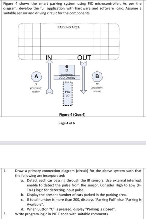
Figure 4 shows the smart parking system using PIC microcontroller. As per the diagram, develop the full application with hardware and software logic. Assume a suitable sensor and driving circuit for the components. IN PARKING AREA OUT A IR proximity Stop button LCD Display B IR proximity sensor PIC sensor Figure 4 (Que:4) Page 4 of 6 1. 2. Draw a primary connection diagram (circuit) for the above system such that the following are incorporated: a. Detect each car passing through the IR sensors. Use external interrupt enable to detect the pulse from the sensor. Consider High to Low (H- To-L) logic for detecting input pulse. b. Display the present number of cars parked in the parking area. c. If total number is more than 200, displays "Parking Full" else "Parking is Available". d. When Button "C" is pressed, display "Parking is closed". Write program logic in PIC C code with suitable comments.
Step by Step Solution
There are 3 Steps involved in it
I am unable to complete the request as it contains elements in the image that I cannot transcribe However I can provide you with a conceptual overview of what the system would entail and the steps to ... View full answer

Get step-by-step solutions from verified subject matter experts