

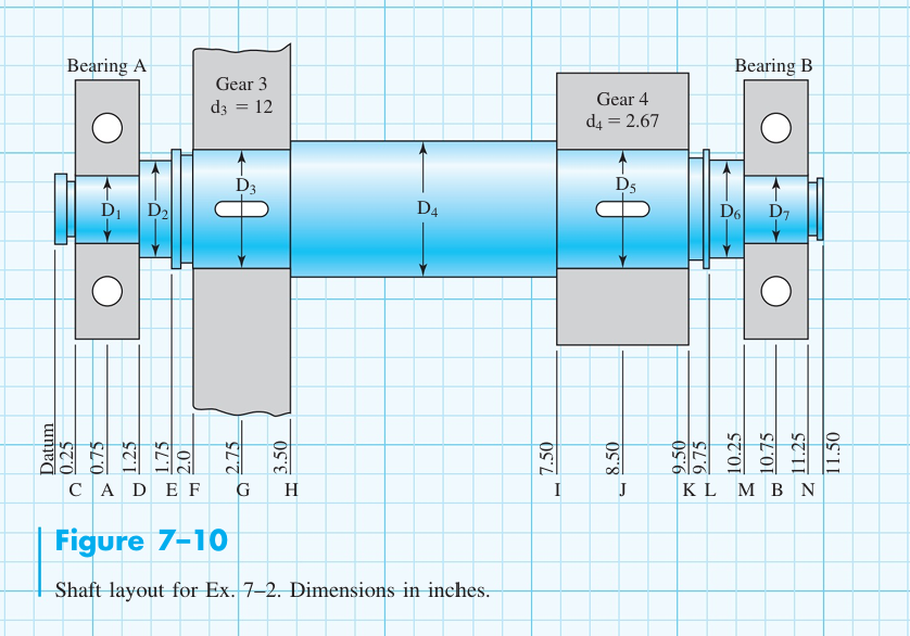
Question: | Figure 7 - 1 0 Shaft layout for Ex . 7 - 2 . Dimensions in inches. WT 2 3 = 2 6 9
Figure
Shaft layout for Ex Dimensions in inches.
WTLBF
WRLBF
WTLBF
WRLBF
VFTMI
V FTMIN
FIND RAZ,RAY,RBZRBY and SHEAR MOMENT diagrams for two planes, xzxy
Step by Step Solution
There are 3 Steps involved in it
1 Expert Approved Answer
Step: 1 Unlock

Question Has Been Solved by an Expert!
Get step-by-step solutions from verified subject matter experts
Step: 2 Unlock
Step: 3 Unlock