

Question: Figure 7 shows the geometry and pipe sizes for another simple pipe network. Each node represents a separate building on the grounds of a manufacturing
Figure shows the geometry and pipe sizes for another simple pipe network. Each node
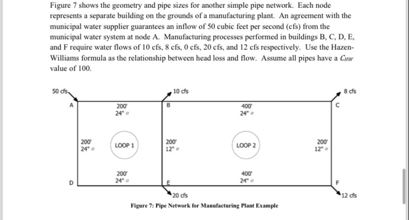
represents a separate building on the grounds of a manufacturing plant. An agreement with the
municipal water supplier guarantees an inflow of cubic feet per second cfs from the
municipal water system at node A Manufacturing processes performed in buildings B C D E
and require water flows of and respectively. Use the Hazen
Williams formula as the relationship between head loss and flow. Assume all pipes have a
value of
Figure : Pipe Network for Manufacturing Plant Example
Step by Step Solution
There are 3 Steps involved in it
1 Expert Approved Answer
Step: 1 Unlock

Question Has Been Solved by an Expert!
Get step-by-step solutions from verified subject matter experts
Step: 2 Unlock
Step: 3 Unlock