

Question: Figure shows a system for batch processing. The operating sequences for the system are given as :- 1. When the start button is pressed, the
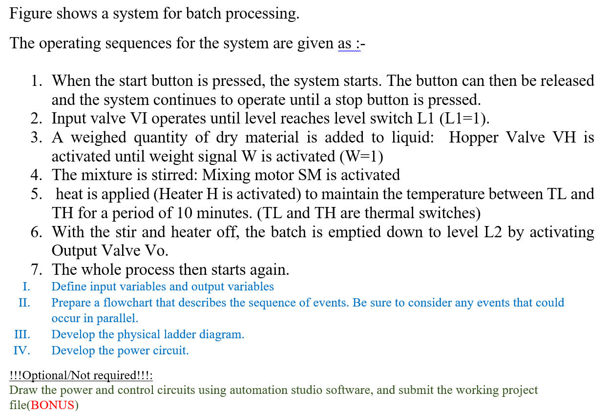
Figure shows a system for batch processing. The operating sequences for the system are given as :- 1. When the start button is pressed, the system starts. The button can then be released and the system continues to operate until a stop button is pressed. 2. Input valve VI operates until level reaches level switch L1 (L1=1). 3. A weighed quantity of dry material is added to liquid: Hopper Valve VH is activated until weight signal W is activated (W=1) 4. The mixture is stirred: Mixing motor SM is activated 5. heat is applied (Heater H is activated) to maintain the temperature between TL and TH for a period of 10 minutes. (TL and TH are thermal switches) 6. With the stir and heater off, the batch is emptied down to level L2 by activating Output Valve Vo. 7. The whole process then starts again. Define input variables and output variables Prepare a flowchart that describes the sequence of events. Be sure to consider any events that could occur in parallel. Develop the physical ladder diagram. IV. Develop the power circuit. I. II. III. !!!Optional/Not required!!!: Draw the power and control circuits using automation studio software, and submit the working project file(BONUS) Figure shows a system for batch processing. The operating sequences for the system are given as :- 1. When the start button is pressed, the system starts. The button can then be released and the system continues to operate until a stop button is pressed. 2. Input valve VI operates until level reaches level switch L1 (L1=1). 3. A weighed quantity of dry material is added to liquid: Hopper Valve VH is activated until weight signal W is activated (W=1) 4. The mixture is stirred: Mixing motor SM is activated 5. heat is applied (Heater H is activated) to maintain the temperature between TL and TH for a period of 10 minutes. (TL and TH are thermal switches) 6. With the stir and heater off, the batch is emptied down to level L2 by activating Output Valve Vo. 7. The whole process then starts again. Define input variables and output variables Prepare a flowchart that describes the sequence of events. Be sure to consider any events that could occur in parallel. Develop the physical ladder diagram. IV. Develop the power circuit. I. II. III. !!!Optional/Not required!!!: Draw the power and control circuits using automation studio software, and submit the working project file(BONUS)
Step by Step Solution
There are 3 Steps involved in it

Get step-by-step solutions from verified subject matter experts