

Question: flop. b) A serial-in, parallel-out shift register (as used within a synchronous communication interface) is traditionally implemented using D-type flip-flops, as shown in Figure
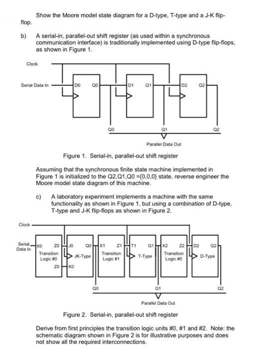
flop. b) A serial-in, parallel-out shift register (as used within a synchronous communication interface) is traditionally implemented using D-type flip-flops, as shown in Figure 1. Show the Moore model state diagram for a D-type, T-type and a J-K flip- Clock Serial Data In Clock Serial Data In XO 20 Transition Logic #0 ZO DO 00 Parallel Data Out Figure 1. Serial-in, parallel-out shift register Assuming that the synchronous finite state machine implemented in Figure 1 is initialized to the Q2,Q1,Q0 =(0,0,0) state, reverse engineer the Moore model state diagram of this machine. JO c) A laboratory experiment implements a machine with the same functionality as shown in Figure 1, but using a combination of D-type, T-type and J-K flip-flops as shown in Figure 2. KO Q0X1 JK-Type D1 QO 01 21 T1 Transition Logic #1 Q1 T-Type D2 02 01 Q2 01x2 22 02 Q2 Transition Logic #0 Parallel Data Out Figure 2. Serial-in, parallel-out shift register D-Type 02 Derive from first principles the transition logic units #0, #1 and # 2. Note: the schematic diagram shown in Figure 2 is for illustrative purposes and does not show all the required interconnections.
Step by Step Solution
3.39 Rating (158 Votes )
There are 3 Steps involved in it
a Moore Model State Diagram for ... View full answer

Get step-by-step solutions from verified subject matter experts