

Question: For circuit shown in Fig. E 2 t - 1 , where the input voltage is ( v _ { i } ( t
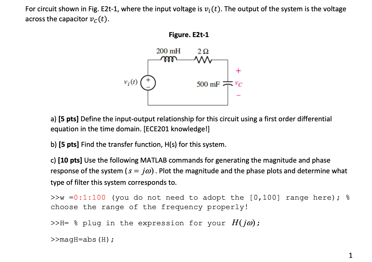
For circuit shown in Fig. Et where the input voltage is vit The output of the system is the voltage across the capacitor vCt
a pts Define the inputoutput relationship for this circuit using a first order differential equation in the time domain. ECE knowledge!
b pts Find the transfer function, mathrmHmathrms for this system.
c pts Use the following MATLAB commands for generating the magnitude and phase response of the system sj omega Plot the magnitude and the phase plots and determine what type of filter this system corresponds to
w ::you do not need to adopt the range here;
choose the range of the frequency properly!
H plug in the expression for your Hjomega;
magHabsH;
angHangle Hpi;
d Apply the sawtooth waveform shown in Textbook Example Fig as the input
voltage vit also shown here as Fig. Et Calculate by hand the output voltage across the capacitor
first pts and plot the vCt using MATLAB pts You can refer to Example on the calculation of
FS
Figure. EtFig in Textbook
e pts bonus Use PSPICE or LTspice to find the output voltage by given the input voltage in
Problem d
Please answer all problems with all steps! Will upvote!
Step by Step Solution
There are 3 Steps involved in it
1 Expert Approved Answer
Step: 1 Unlock

Question Has Been Solved by an Expert!
Get step-by-step solutions from verified subject matter experts
Step: 2 Unlock
Step: 3 Unlock