

Question: FOR COPY AND PASTE int sensorPin = 0; // select the analog input pin for the photoresistor int bPin = 9; // select the digital
FOR COPY AND PASTE
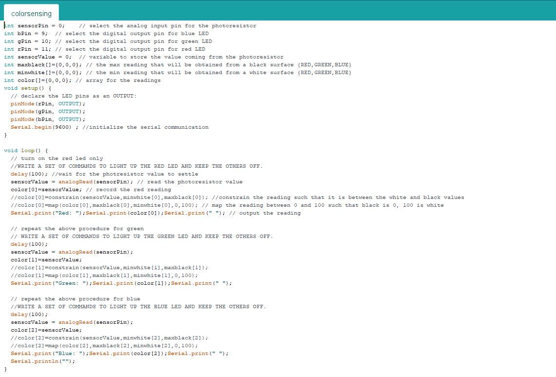
int sensorPin = 0; // select the analog input pin for the photoresistor int bPin = 9; // select the digital output pin for blue LED int gPin = 10; // select the digital output pin for green LED int rPin = 11; // select the digital output pin for red LED int sensorValue = 0; // variable to store the value coming from the photoresistor int maxblack[]={0,0,0}; // the max reading that will be obtained from a black surface {RED,GREEN,BLUE} int minwhite[]={0,0,0}; // the min reading that will be obtained from a white surface {RED,GREEN,BLUE} int color[]={0,0,0}; // array for the readings void setup() { // declare the LED pins as an OUTPUT: pinMode(rPin, OUTPUT); pinMode(gPin, OUTPUT); pinMode(bPin, OUTPUT); Serial.begin(9600) ; //initialize the serial communication }
void loop() { // turn on the red led only //WRITE A SET OF COMMANDS TO LIGHT UP THE RED LED AND KEEP THE OTHERS OFF. delay(100); //wait for the photresistor value to settle sensorValue = analogRead(sensorPin); // read the photoresistor value color[0]=sensorValue; // record the red reading //color[0]=constrain(sensorValue,minwhite[0],maxblack[0]); //constrain the reading such that it is between the white and black values //color[0]=map(color[0],maxblack[0],minwhite[0],0,100); // map the reading between 0 and 100 such that black is 0, 100 is white Serial.print("Red: ");Serial.print(color[0]);Serial.print(" "); // output the reading // repeat the above procedure for green // WRITE A SET OF COMMANDS TO LIGHT UP THE GREEN LED AND KEEP THE OTHERS OFF. delay(100); sensorValue = analogRead(sensorPin); color[1]=sensorValue; //color[1]=constrain(sensorValue,minwhite[1],maxblack[1]); //color[1]=map(color[1],maxblack[1],minwhite[1],0,100); Serial.print("Green: ");Serial.print(color[1]);Serial.print(" "); // repeat the above procedure for blue //WRITE A SET OF COMMANDS TO LIGHT UP THE BLUE LED AND KEEP THE OTHERS OFF. delay(100); sensorValue = analogRead(sensorPin); color[2]=sensorValue; //color[2]=constrain(sensorValue,minwhite[2],maxblack[2]); //color[2]=map(color[2],maxblack[2],minwhite[2],0,100); Serial.print("Blue: ");Serial.print(color[2]);Serial.print(" "); Serial.println("");
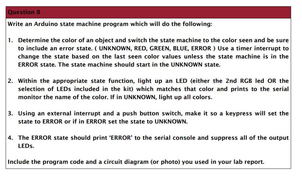
Question 8 Write an Arduino state machine program which will do the following: 1. Determine the color of an object and switch the state machine to the color seen and be sure to include an error state. ( UNKNOWN, RED, GREEN, BLUE, ERROR) Use a timer interrupt to change the state based on the last seen color values unless the state machine is in the ERROR state. The state machine should start in the UNKNOWN state. 2. Within the appropriate state function, light up an LED (either the 2nd RGB led OR the selection of LEDs included in the kit) which matches that color and prints to the serial monitor the name of the color. If in UNKNOWN, light up all colors. 3. Using an external interrupt and a push button switch, make it so a keypress will set the state to ERROR or if in ERROR set the state to UNKNOWN. 4. The ERROR state should print 'ERROR' to the serial console and suppress all of the output LEDs. Include the program code and a circuit diagram (or photo) you used in your lab report. colorsensing int sensorPin = 0; // select the analog input pin for the photoresistor int bPin = 9; // select the digital output pin for blue LED int gPin = 10; // select the digital output pin for green LED int Pin = ll; // select the digital output pin for red LED int sensorValue . 0; // variable to store the value coming from the photoresistor int maxblack[]={0,0,0); // the max reading that will be obtained from a black surface (RED, GREEN, BLUE) int minwhite[]={0,0,0}; // the min reading that will be obtained from a white surface {RED, GREEN, BLUE) int color[]=[0,0,0); // array for the readings void setup() { // declare the LED pins as an OUTPUT: pinMode(rPin, OUTPUT); pinMode(gPin, OUTPUT); pinMode(bPin, OUTPUT); Serial.begin(9600); //initialize the serial communication } void loop() { // turn on the red led only //WRITE A SET OF COMMANDS TO LIGHT UP THE RED LED AND KEEP THE OTHERS OFF. delay(100); //wait for the photresistor value to settle sensorValue = analogRead(sensorPin); // read the photoresistor value color[0]=sensorValue; // record the red reading //color[0]=constrain(sensorValue, minwhite[0], maxblack[0]); // constrain the reading such that it is between the white and black values //color[0]=map (color[0], maxblack[0], minwhite[0], 0, 100); // map the reading between 0 and 100 such that black is o, 100 is white Serial.print("Red: "); Serial.print (color [0]); Serial.print(" "); // output the reading // repeat the above procedure for green // WRITE A SET OF COMMANDS TO LIGHT UP THE GREEN LED AND KEEP THE OTHERS OFF. delay(100); sensorValue = analogRead(sensor Pin); color[1]=sensorValue; //color[1]=constrain (sensorValue, minwhite[1], maxblack[1]); //color[1]=map (color[1], maxblack [1], minwhite[1], 0,100); Serial.print("Green: "); Serial.print(color[1]); Serial.print(" "); repeat the above procedure for blue //WRITE A SET OF COMMANDS TO LIGHT UP THE BLUE LED AND KEEP THE OTHERS OFF. delay(100); sensorValue = analogRead(sensor Pin), color [2]=sensorValue; //color[2]=constrain (sensorValue, minwhite [2], maxblack[2]); //color [2] =map (color [2], maxblack [2], minwhite [2],0,100); Serial.print("Blue: "); Serial.print(color[2]); Serial.print(" "); Serial.println(""); } Question 8 Write an Arduino state machine program which will do the following: 1. Determine the color of an object and switch the state machine to the color seen and be sure to include an error state. ( UNKNOWN, RED, GREEN, BLUE, ERROR) Use a timer interrupt to change the state based on the last seen color values unless the state machine is in the ERROR state. The state machine should start in the UNKNOWN state. 2. Within the appropriate state function, light up an LED (either the 2nd RGB led OR the selection of LEDs included in the kit) which matches that color and prints to the serial monitor the name of the color. If in UNKNOWN, light up all colors. 3. Using an external interrupt and a push button switch, make it so a keypress will set the state to ERROR or if in ERROR set the state to UNKNOWN. 4. The ERROR state should print 'ERROR' to the serial console and suppress all of the output LEDs. Include the program code and a circuit diagram (or photo) you used in your lab report. colorsensing int sensorPin = 0; // select the analog input pin for the photoresistor int bPin = 9; // select the digital output pin for blue LED int gPin = 10; // select the digital output pin for green LED int Pin = ll; // select the digital output pin for red LED int sensorValue . 0; // variable to store the value coming from the photoresistor int maxblack[]={0,0,0); // the max reading that will be obtained from a black surface (RED, GREEN, BLUE) int minwhite[]={0,0,0}; // the min reading that will be obtained from a white surface {RED, GREEN, BLUE) int color[]=[0,0,0); // array for the readings void setup() { // declare the LED pins as an OUTPUT: pinMode(rPin, OUTPUT); pinMode(gPin, OUTPUT); pinMode(bPin, OUTPUT); Serial.begin(9600); //initialize the serial communication } void loop() { // turn on the red led only //WRITE A SET OF COMMANDS TO LIGHT UP THE RED LED AND KEEP THE OTHERS OFF. delay(100); //wait for the photresistor value to settle sensorValue = analogRead(sensorPin); // read the photoresistor value color[0]=sensorValue; // record the red reading //color[0]=constrain(sensorValue, minwhite[0], maxblack[0]); // constrain the reading such that it is between the white and black values //color[0]=map (color[0], maxblack[0], minwhite[0], 0, 100); // map the reading between 0 and 100 such that black is o, 100 is white Serial.print("Red: "); Serial.print (color [0]); Serial.print(" "); // output the reading // repeat the above procedure for green // WRITE A SET OF COMMANDS TO LIGHT UP THE GREEN LED AND KEEP THE OTHERS OFF. delay(100); sensorValue = analogRead(sensor Pin); color[1]=sensorValue; //color[1]=constrain (sensorValue, minwhite[1], maxblack[1]); //color[1]=map (color[1], maxblack [1], minwhite[1], 0,100); Serial.print("Green: "); Serial.print(color[1]); Serial.print(" "); repeat the above procedure for blue //WRITE A SET OF COMMANDS TO LIGHT UP THE BLUE LED AND KEEP THE OTHERS OFF. delay(100); sensorValue = analogRead(sensor Pin), color [2]=sensorValue; //color[2]=constrain (sensorValue, minwhite [2], maxblack[2]); //color [2] =map (color [2], maxblack [2], minwhite [2],0,100); Serial.print("Blue: "); Serial.print(color[2]); Serial.print(" "); Serial.println(""); }
Step by Step Solution
There are 3 Steps involved in it

Get step-by-step solutions from verified subject matter experts