

Question: The objective of this project is to design a controller Ge(s) for a given plant with transfer function: G, (s) = s(s+5)(s+10) For this
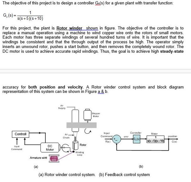
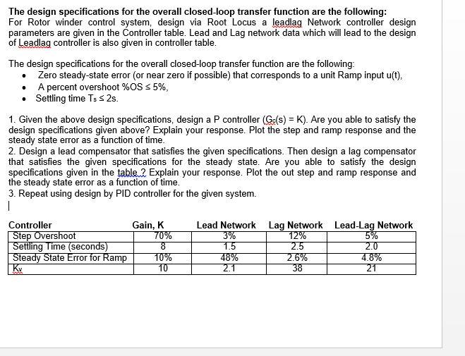
The objective of this project is to design a controller Ge(s) for a given plant with transfer function: G, (s) = s(s+5)(s+10) For this project, the plant is Rotor winder shown in figure. The objective of the controller is to replace a manual operation using a machine to wind copper wire onto the rotors of small motors. Each motor has three separate windings of several hundred turns of wire. It is important that the windings be consistent and that the through output of the process be high. The operator simply inserts an unwound rotor, pushes a start button, and then removes the completely wound rotor. The DC motor is used to achieve accurate rapid windings. Thus, the goal is to achieve high steady-state accuracy for both position and velocity. A Rotor winder control system and block diagram representation of this system can be shown in Figure a & b. Air Supply Stepper Motor Controller Controll Input Command, Mator Air emor posiion Chuck G.(5 Rs) s(s + 5)(s+ 10) C(s) Rotor DC Input Command Motor Winding Loop Armature wire (a) (b) (a) Rotor winder control system. (b) Feedback control system The design specifications for the overall closed-loop transfer function are the following: For Rotor winder control system, design via Root Locus a leadlag Network controller design parameters are given in the Controller table. Lead and Lag network data which will lead to the design of Leadlag controller is also given in controller table. The design specifications for the overall closed-loop transfer function are the following: Zero steady-state error (or near zero if possible) that corresponds to a unit Ramp input u(t), A percent overshoot %OS s 5%, Settling time Ts s 2s. 1. Given the above design specifications, design a P controller (Ge(s) = K). Are you able to satisfy the design specifications given above? Explain your response. Plot the step and ramp response and the steady state error as a function of time. 2. Design a lead compensator that satisfies the given specifications. Then design a lag compensator that satisfies the given specifications for the steady state. Are you able to satisfy the design specifications given in the table 2 Explain your response. Plot the out step and ramp response and the steady state error as a function of time. 3. Repeat using design by PID controller for the given system. Controller Step Overshoot Settling Time (seconds) Steady State Error for Ramp Kv Gain, K 70% Lead Network Lag Network Lead-Lag Network 12% 2.5 2.6% 38 3% 1.5 48% 2.1 5% 2.0 4.8% 21 10% 10
Step by Step Solution
3.42 Rating (158 Votes )
There are 3 Steps involved in it
Image... View full answer

Get step-by-step solutions from verified subject matter experts