

Question: For the analysis and procedure (Step 5 and 6) this needs to be calculated using figure 5. Results for Step 2 (procedure and analysis): Results
For the analysis and procedure (Step 5 and 6) this needs to be calculated using figure 5.


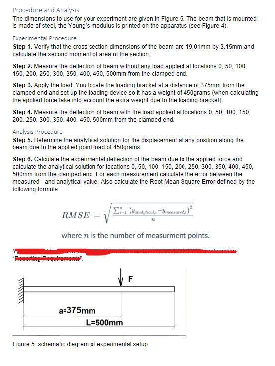
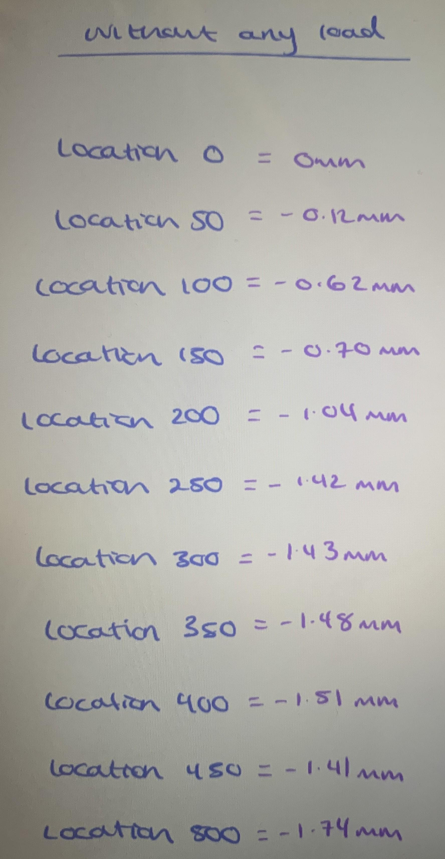
Results for Step 2 (procedure and analysis):
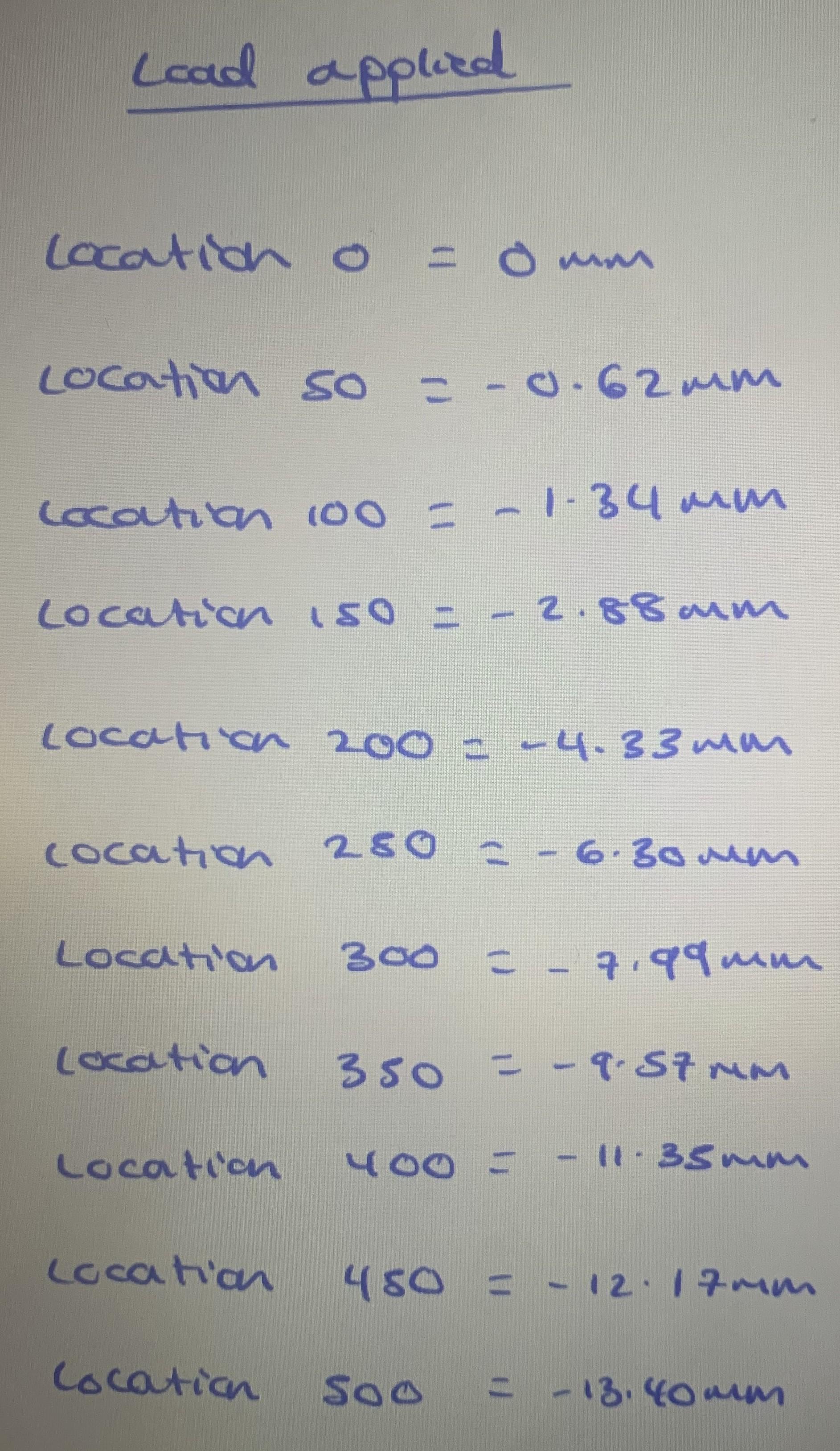
Results for Step 3/4:
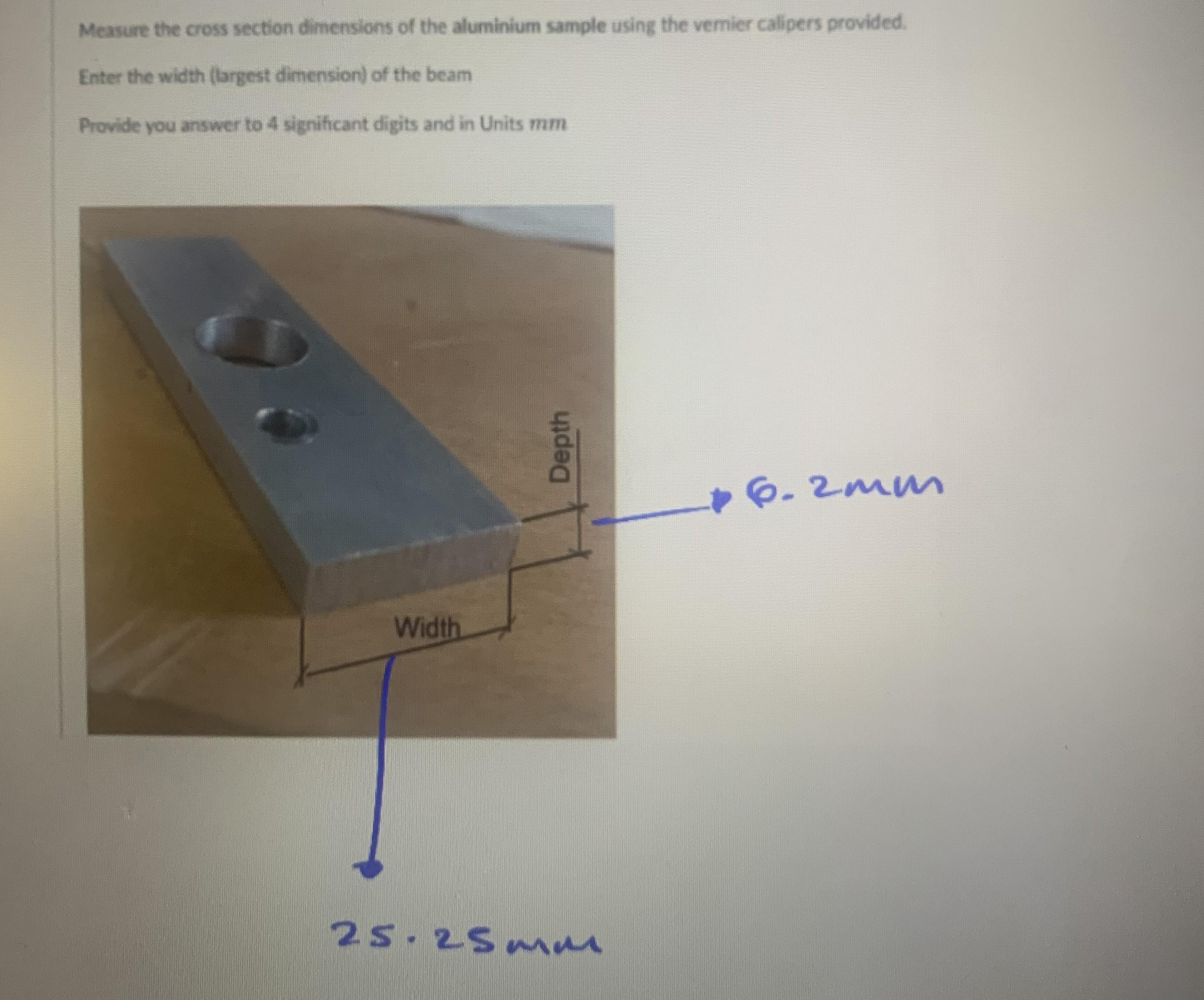
Question 1:
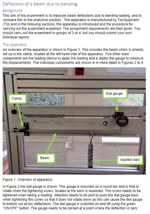
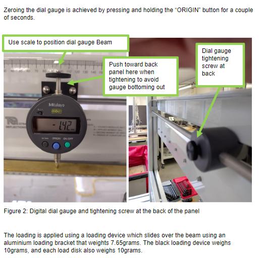
Deflection of a beam due to bending Background This aim of this experiment is to measure beam deflections due to bending loading, and to compare this to the analytical solution. The apparatus is manufactured by TecQuipment (TQ) and in the following sections, the apparatus is introduced and the procedure for carrying out the experiment explained. The assignment requirements are then given. You should carry out the experiment in groups of 3 or 4, but you should submit your own individual reports. The Apparatus An overview of the apparatus is shown in Figure 1. This includes the beam which is already set up in the clamp, located at the left-hand side of the apparatus. Two other main components are the loading device to apply the loading and a digital dial gauge to measure the displacements. The individual components are shown in in more detail in Figures 2 to 4. Clamp Beam Dial gauge Applied load Figure 1: Overview of apparatus In Figure 2 the dial gauge is shown. This gauge is mounted on a round bar and is free to rotate when the tightening screw, located at the back is loosened. This screw needs to be tightened when taking a reading. Attention needs to be paid to push the dial gauge back when tightening this screw so that it does not rotate down as this can cause the dial gauge to bottom out at low deflections. The dial gauge is switched on and off using the green "ON/OFF" button. The gauge needs to be zeroed at a point where the deflection is zero.
Step by Step Solution
There are 3 Steps involved in it
You have provided extensive information on an experimental procedure to measure the deflection of a beam under bending loads as well as a series of questions that need to be answered using the given d... View full answer

Get step-by-step solutions from verified subject matter experts