

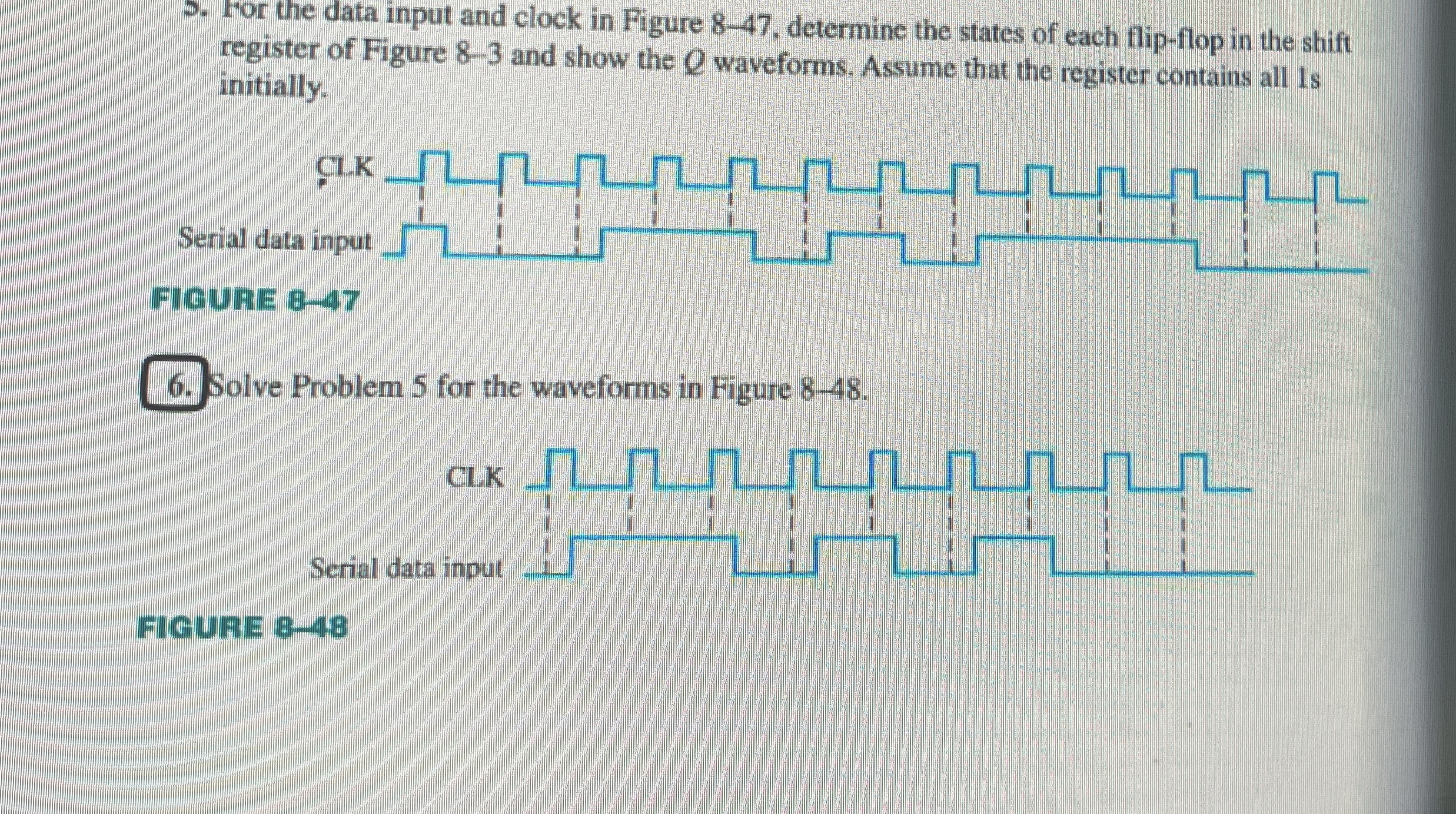
Question: For the data input and clock in Figure 8 - 4 7 , determine the states of each flip - flop in the shift register
For the data input and clock in Figure determine the states of each flipflop in the shift register of Figure and show the waveforms. Assume that the register contains all s initially.
Fig
Solve Problem for the waveforms in Figure
Serial data input
L
L
FIGURE
Show the waveforms of Q in problem
Step by Step Solution
There are 3 Steps involved in it
1 Expert Approved Answer
Step: 1 Unlock

Question Has Been Solved by an Expert!
Get step-by-step solutions from verified subject matter experts
Step: 2 Unlock
Step: 3 Unlock