

Question: 1.Assume that a 4-bit serial in/serial out (SISO) shift register is initially clear. Data 1100 is serially entered. What will be the 4-bit pattern after
1.Assume that a 4-bit serial in/serial out (SISO) shift register is initially clear. Data 1100 is serially entered. What will be the 4-bit pattern after the second clock pulse? (MSB bit first) A) 1100 B) 0011 C) 0000 D) 1111 2.A series of bits 10110111 is serially shifted (LSB bit first) into an 8-bit parallel output (SIPO) shift register with an initial state 11110000. After the second clock pulse, the register contains ________. A) 10111000 B) 10110111 C) 11110000 D) 11111100 3.How many unique states are in an 8-bit Johnson counter? A) 4 B) 8 C) 16 D) 64 4.Assume Q3 is the output of the last FF. On the fifth clock pulse, a 4-bit Johnson sequence is Q0 = 0, Q1 = 1, Q2 = 1, and Q3 = 1. What is the sequence on the sixth clock pulse? A) Q0 = 1, Q1 = 0, Q2 = 0, Q3 = 0 B) Q0 = 1, Q1 = 1, Q2 = 1, Q3 = 1 C) Q0 = 0, Q1 = 0, Q2 = 1, Q3 = 1 D) Q0 = 0, Q1 = 0, Q2 = 0, Q3 = 1 5.Which of the following functions can be used to detect how many empty slots available in a parking lot? A) Encoder B) Comparator C) Multiplexer D) Parity Generator 6.What gates should you use to decode the binary number 0011 with an active-LOW decoder? A) OR and NAND gates B) AND and NOR gates C) NOT and AND gates D) NOT and NAND gates 7.Which statement about DEMUX is FALSE? A) It is also known as data selector. B) A decoder can also be used as a DEMUX. C) A DEMUX reverses the function of a MUX. D) It takes digital information from one line and distributes it to a given number of output lines. 8.Choose the TRUE statement regarding parity checker. A) Parity checker is used to correct an error in the received data. B) Parity checker is used to determine numbers of bit 1 in the data. C) OR gate is used in parity checker to check for inequality. D) Parity checker is produced using parallel adder. 9.Which of the statement is FALSE about latch and flip-flop? A) Both devices are memory elements. B) Both devices need clock input in order to change the output state. C) Latch output is fully dependent on input level triggered. D) Flip-flop output is changing at either at negative or positive clock triggered. 10.If the data select lines of the MUX in Figure 1 are S1S0 = 11, what would the output be? 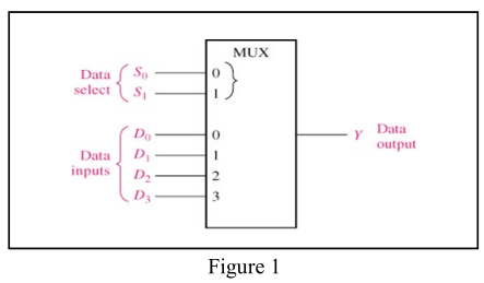
A) LOW B) HIGH C) Equal to D0 D) Equal to D3 11.Which of the statement is TRUE about sequential logic circuit versus combinational logic circuit design? A) Both circuits have closed loop feedback from output to the input. B) Gated-SR flip flop can be included in combinational logic circuit. C) Clock must be supplied to the input in the combinational logic circuit. D) Sequential logic circuit must have memory element device. 12.Choose the TRUE statement about the output of S-R flip-flop. 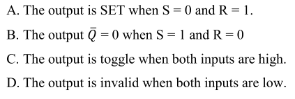 13.Choose the FALSE statement regarding the flip-flop asynchronous input:
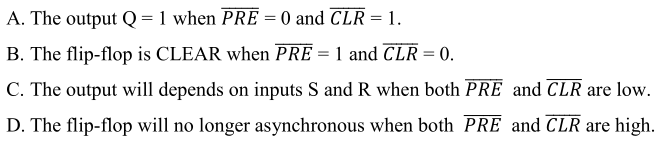
14.The output Q can be represented by the following flip-flop (negative-edged clock) EXCEPT: 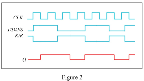
A) S-R flip-flop. B) J-K flip-flop. C) D flip-flop. D) T flip-flop 15.Which of the following is considered as medium priority input(s)?  16.Choose the CORRECT statement about asynchronous counter. A) Low-frequency applications are limited because of internal propagation delays. B) High-frequency applications are limited because of internal propagation delays. C) Asynchronous counters are suitable for use in high- and low-frequency counting applications. D) Asynchronous counters do not have propagation delays and this limits their use in high-frequency applications. 17. How many flip-flops are required to produce MOD 32 binary counter? A) 3 B) 45 C) 5 D) 6 18.Three cascaded MOD 5 counters have an overall modulus of ________. A) 5 B) 25 C) 125 D) 500
MUX Data select {S: S. S 1:3 1 DO 0 Y Data output D 1 Data inputs 2 D; 3 Figure 1 A. The output is SET when S = 0) and R = 1. B. The output ( = 0 when S = 1 and R=0 C. The output is toggle when both inputs are high. D. The output is invalid when both inputs are low. A. The output Q=1 when PRE = 0 and CLR = 1. B. The flip-flop is CLEAR when PRE = 1 and CLR = 0. C. The output will depends on inputs S and R when both PRE and CLR are low. D. The flip-flop will no longer asynchronous when both PRE and CLR are high. CLK T/D/J/S KR Q Figure 2 A. Clock C.T B. PRE D. J and K
Step by Step Solution
There are 3 Steps involved in it

Get step-by-step solutions from verified subject matter experts