

Question: For the filtered bridge rectifier with a load as indicated in the figure shown below. 8:2 All diodes are silicon diodes D D Determine:
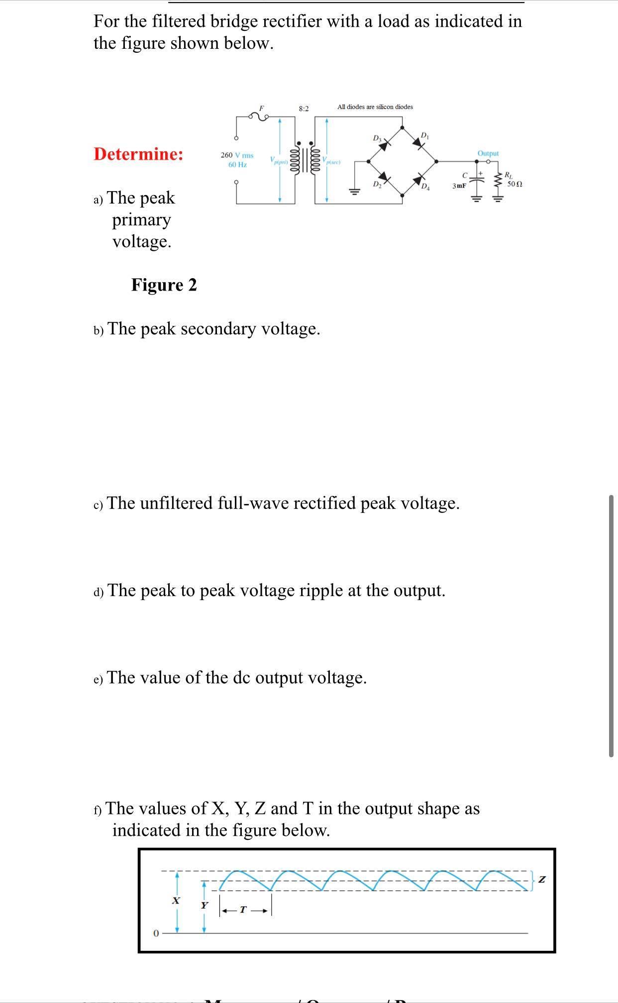
For the filtered bridge rectifier with a load as indicated in the figure shown below. 8:2 All diodes are silicon diodes D D Determine: Output 260 V rms 60 Hz pipri) plsee) R 502 C D2 3 mF a) The peak primary voltage. Figure 2 b) The peak secondary voltage. c) The unfiltered full-wave rectified peak voltage. d) The peak to peak voltage ripple at the output. e) The value of the dc output voltage. ) The values of X, Y, Z and T in the output shape as indicated in the figure below. lll
Step by Step Solution
3.55 Rating (172 Votes )
There are 3 Steps involved in it
a Peak primary voltage22603677 V b Peak secondary v... View full answer

Get step-by-step solutions from verified subject matter experts