

Question: For the lab assignment, you are to model and simulate the system shown in Fig. 5. The inputs are the torque on the left,
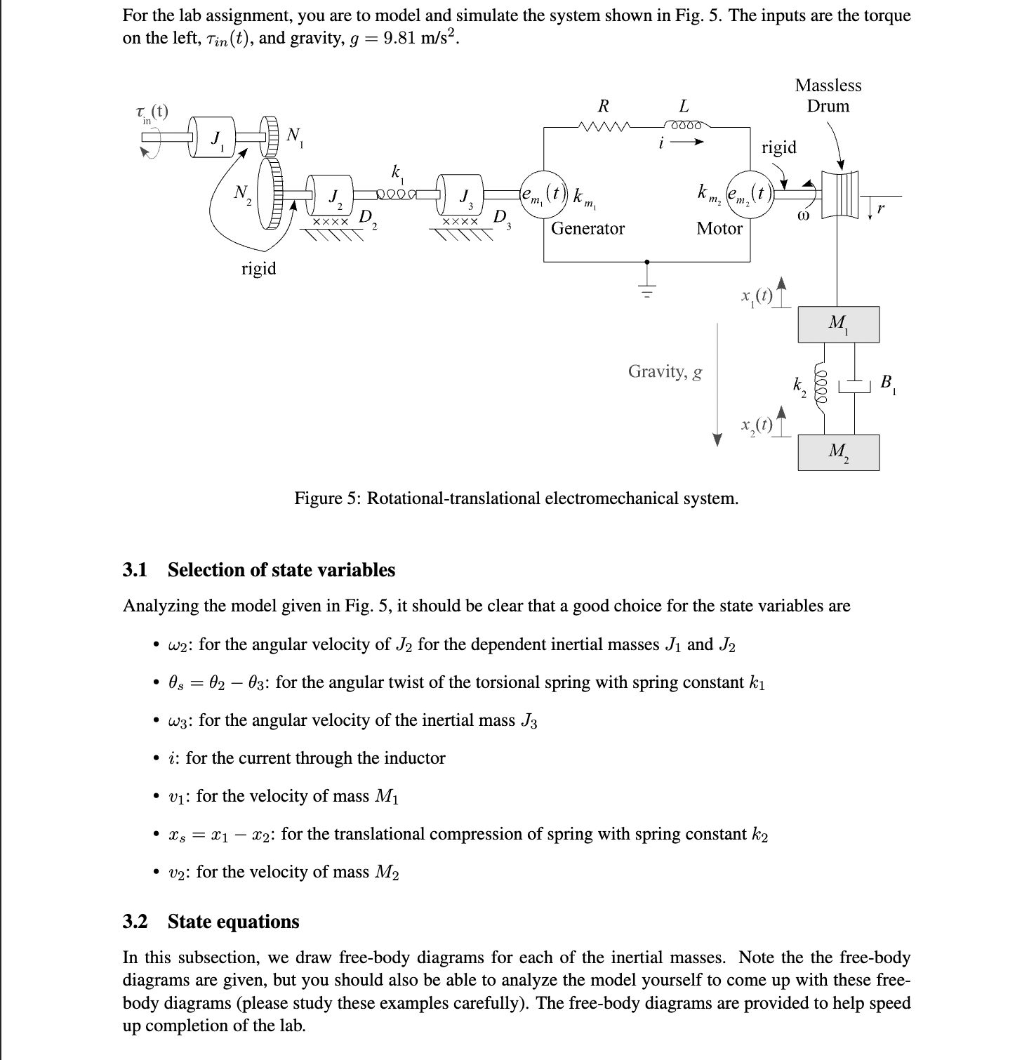
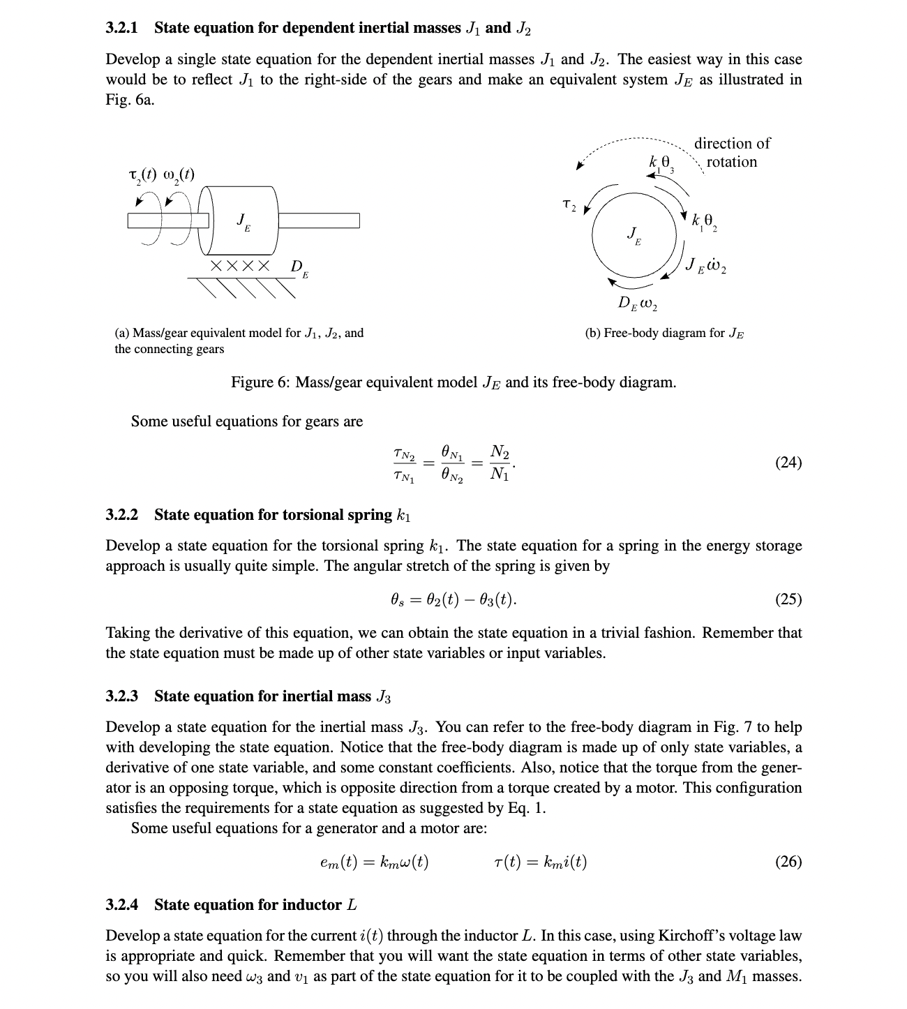
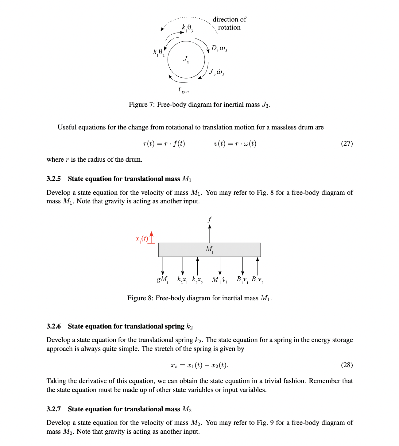
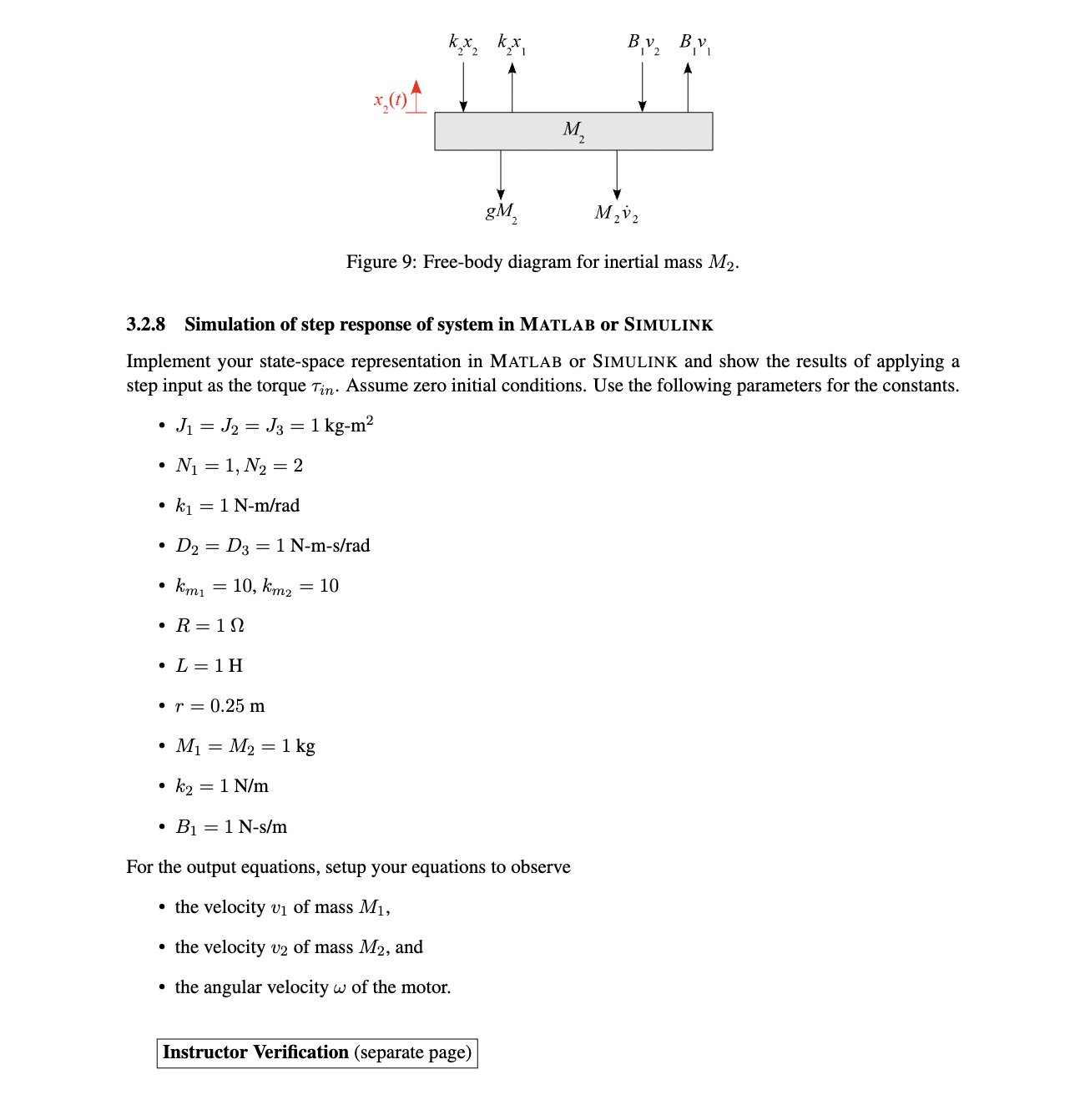
For the lab assignment, you are to model and simulate the system shown in Fig. 5. The inputs are the torque on the left, Tin(t), and gravity, g = 9.81 m/s. T. (t) in rigid N XXXX 2 pooa XXXX 3 R L Massless Drum ww 0000 i rigid e n,(t)) k, kmem,(t) m Generator Motor Gravity, g x(t) M 0000 B x(t) M Figure 5: Rotational-translational electromechanical system. 3.1 Selection of state variables Analyzing the model given in Fig. 5, it should be clear that a good choice for the state variables are w2: for the angular velocity of J2 for the dependent inertial masses J1 and J2 0s = 02 - 03: for the angular twist of the torsional spring with spring constant ki w3: for the angular velocity of the inertial mass J3 i: for the current through the inductor v1: for the velocity of mass M x = x1 = x2: for the translational compression of spring with spring constant k2 V2: for the velocity of mass M2 3.2 State equations In this subsection, we draw free-body diagrams for each of the inertial masses. Note the the free-body diagrams are given, but you should also be able to analyze the model yourself to come up with these free- body diagrams (please study these examples carefully). The free-body diagrams are provided to help speed up completion of the lab. 3.2.1 State equation for dependent inertial masses J and J Develop a single state equation for the dependent inertial masses J and J2. The easiest way in this case would be to reflect J to the right-side of the gears and make an equivalent system JE as illustrated in Fig. 6a. T(t) w(t) XXXX D. E k direction of rotation 52 ' k , DEW (b) Free-body diagram for JE (a) Mass/gear equivalent model for J1, J2, and the connecting gears Figure 6: Mass/gear equivalent model JE and its free-body diagram. Some useful equations for gears are ON N2 TN2 TN1 0N2 N (24) 3.2.2 State equation for torsional spring ki Develop a state equation for the torsional spring k. The state equation for a spring in the energy storage approach is usually quite simple. The angular stretch of the spring is given by 0s02(t)-03(t). = (25) Taking the derivative of this equation, we can obtain the state equation in a trivial fashion. Remember that the state equation must be made up of other state variables or input variables. 3.2.3 State equation for inertial mass J3 Develop a state equation for the inertial mass J3. You can refer to the free-body diagram in Fig. 7 to help with developing the state equation. Notice that the free-body diagram is made up of only state variables, a derivative of one state variable, and some constant coefficients. Also, notice that the torque from the gener- ator is an opposing torque, which is opposite direction from a torque created by a motor. This configuration satisfies the requirements for a state equation as suggested by Eq. 1. Some useful equations for a generator and a motor are: em (t) = kmw(t) T(t) = kmi(t) (26) 3.2.4 State equation for inductor L Develop a state equation for the current i(t) through the inductor L. In this case, using Kirchoff's voltage law is appropriate and quick. Remember that you will want the state equation in terms of other state variables, so you will also need w3 and V as part of the state equation for it to be coupled with the J3 and M masses. k , direction of rotation D3 W3 gen Figure 7: Free-body diagram for inertial mass J3. Useful equations for the change from rotational to translation motion for a massless drum are T(t) = =r. f(t) where r is the radius of the drum. v(t) = r. w(t) (27) 3.2.5 State equation for translational mass M Develop a state equation for the velocity of mass M. You may refer to Fig. 8 for a free-body diagram of mass M1. Note that gravity is acting as another input. x(t) M gM kx kx Mv 1 1 Bv BV Figure 8: Free-body diagram for inertial mass M. 3.2.6 State equation for translational spring k2 Develop a state equation for the translational spring k. The state equation for a spring in the energy storage approach is always quite simple. The stretch of the spring is given by xs x1 x1(t) x2(t). (28) Taking the derivative of this equation, we can obtain the state equation in a trivial fashion. Remember that the state equation must be made up of other state variables or input variables. 3.2.7 State equation for translational mass M2 Develop a state equation for the velocity of mass M2. You may refer to Fig. 9 for a free-body diagram of mass M2. Note that gravity is acting as another input. kxkx BV2 BV x(t)' M gM M2v2 Figure 9: Free-body diagram for inertial mass M2. 3.2.8 Simulation of step response of system in MATLAB or SIMULINK Implement your state-space representation in MATLAB or SIMULINK and show the results of applying a step input as the torque Tin. Assume zero initial conditions. Use the following parameters for the constants. J = J = J3 = 1 kg-m N = 1, N2 = 2 k = 1 N-m/rad D2 D3 = 1 N-m-s/rad km1 = = 10, km2 = 10 R= 1 L = 1H r = 0.25 m M = M2 = 1 kg k = 1 N/m B = 1 N-s/m For the output equations, setup your equations to observe the velocity v of mass M, the velocity v2 of mass M2, and the angular velocity w of the motor. Instructor Verification (separate page) Sec. 3: Give the state equations with values plugged in for the system in Fig. 5: W = WE = W3 (2) .5 8. v2 = Sec. 3: Give the output equations for the system in Fig. 5: V = V2= =3 Sec. 3: Simulate the system in Fig. 5 with a step input for the input torque Tin(t):
Step by Step Solution
There are 3 Steps involved in it

Get step-by-step solutions from verified subject matter experts