

Question: For the lever system component calculation chart, arrange the lever components as listed for each task a . through j . Determine the lever class
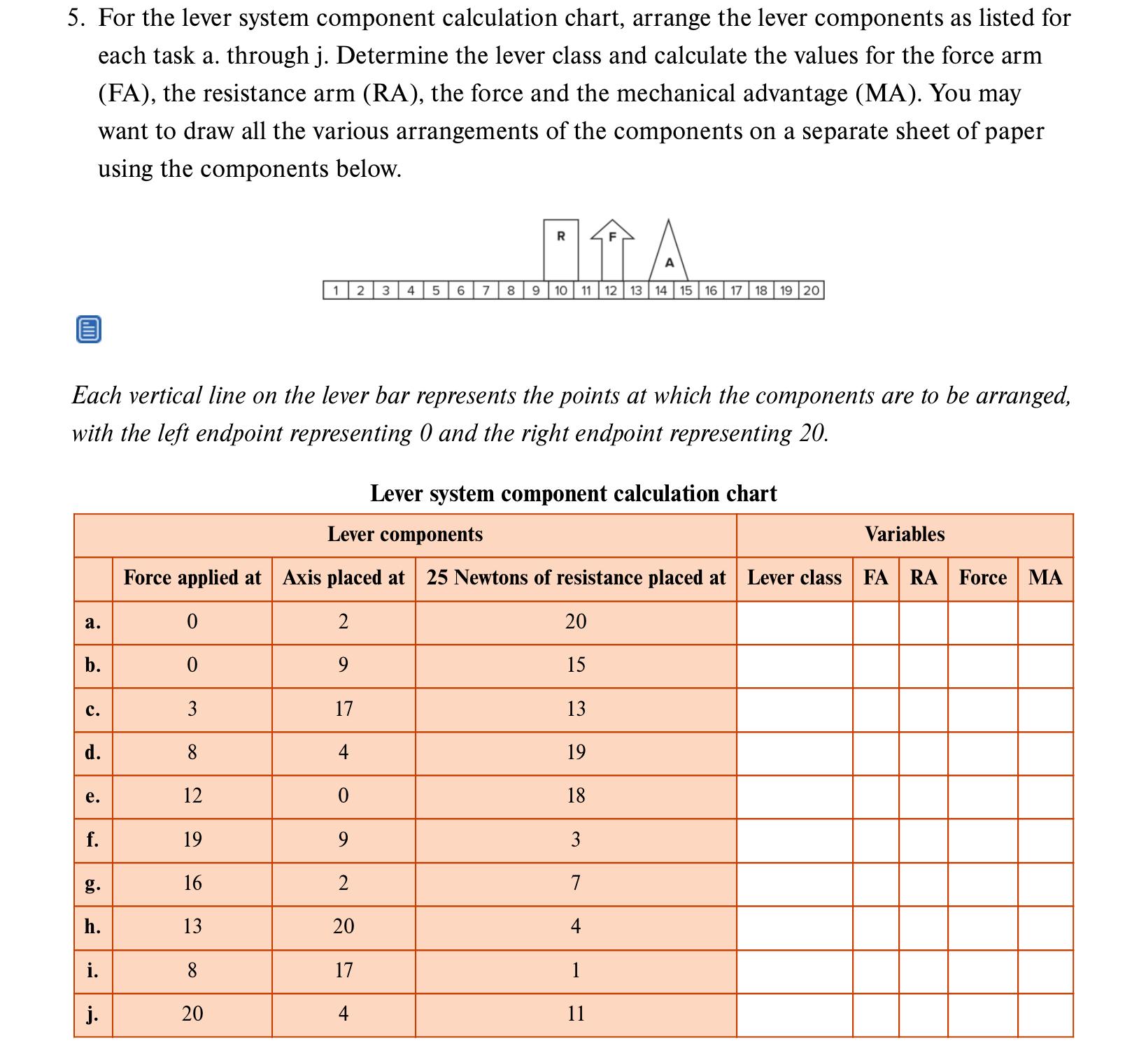
For the lever system component calculation chart, arrange the lever components as listed for each task a through Determine the lever class and calculate the values for the force arm FA the resistance arm RA the force and the mechanical advantage MA You may want to draw all the various arrangements of the components on a separate sheet of paper using the components below.
Each vertical line on the lever bar represents the points at which the components are to be arranged, with the left endpoint representing and the right endpoint representing
Lever system component calculation chart
tableLever components,VariablesForce applied atAxis placed at Newtons of resistance placed atLever class,FARAForce,MAabcdefghij
Step by Step Solution
There are 3 Steps involved in it
1 Expert Approved Answer
Step: 1 Unlock

Question Has Been Solved by an Expert!
Get step-by-step solutions from verified subject matter experts
Step: 2 Unlock
Step: 3 Unlock