

Question: For the shown network below in Figure 1 , a ) Estimate the flow in pipe 1 ; b ) Using the mass conservations at
For the shown network below in Figure
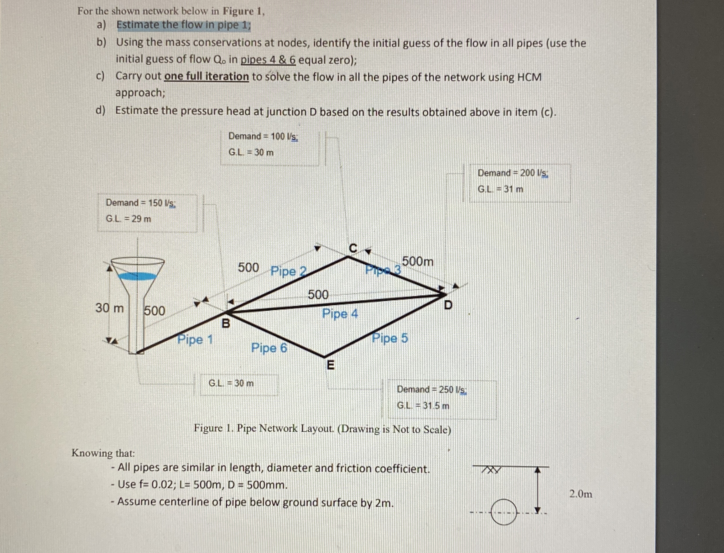
a Estimate the flow in pipe ;
b Using the mass conservations at nodes, identify the initial guess of the flow in all pipes use the
initial guess of flow in pipes & equal zero;
c Carry out one full iteration to solve the flow in all the pipes of the network using HCM
approach;
d Estimate the pressure head at junction D based on the results obtained above in item c
Demand :
Demand
Figure Pipe Network Layout. Drawing is Not to Scale
Knowing that:
All pipes are similar in length, diameter and friction coefficient.
Use ;
Assume centerline of pipe below ground surface by m
Step by Step Solution
There are 3 Steps involved in it
1 Expert Approved Answer
Step: 1 Unlock

Question Has Been Solved by an Expert!
Get step-by-step solutions from verified subject matter experts
Step: 2 Unlock
Step: 3 Unlock