

Question: For the system depicted in Fig(a), the transfer-function blocks are defined by G(s) and (a) Using rlocus and rlocfind, determine the value of K at
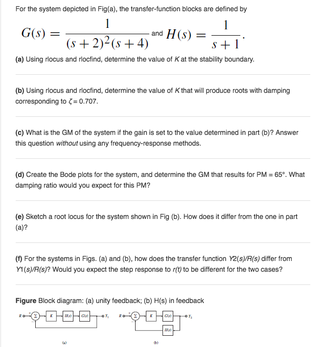
For the system depicted in Fig(a), the transfer-function blocks are defined by G(s) and (a) Using rlocus and rlocfind, determine the value of K at the stability boundary. (b) Using rlocus and rlocfind, determine the value of K that will produce roots with damping corresponding to -0.707. (c) What is the GM of the system if the gain is set to the value determined in part (b)? Answer this question without using any frequency-response methods. (d) Create the Bode plots for the system, and determine the GM that results for PM 659. What damping ratio would you expect for this PM? (e) Sketch a root locus for the system shown in Fig (b). How does it differ from the one in part (a)? (f) For the systems in Figs. (a) and (b), how does the transfer function Y2(s)/R(s) differ from Y1(s)/R(s)? Would you expect the step response to r(t) to be different for the two cases? Figure Block diagram: (a) unity feedback; (b) H(s) in feedback b)
Step by Step Solution
There are 3 Steps involved in it

Get step-by-step solutions from verified subject matter experts