

Question: For this lab you will implement a basic 4 - bit ALU. Our ALU will take in two 4 - bit inputs, perform a selected
For this lab you will implement a basic bit ALU. Our ALU will take in two bit inputs,
perform a selected operation, then output the result. The four operations our ALU will
implement will be: ADD, AND, NOT, and EQUALITY
Getting Started
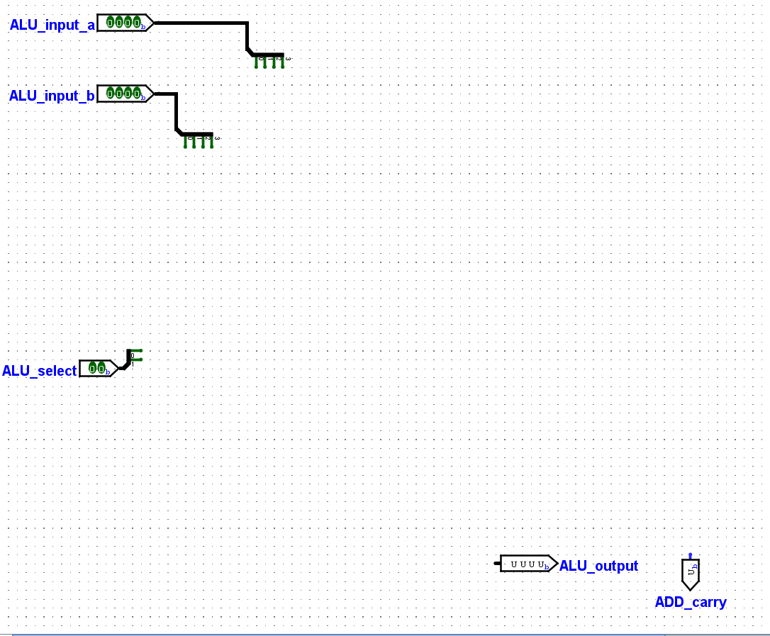
Open the provided Labtemplate project in Logisim. You'll see several inputs and outputs
already added to the circuit. They are:
Two bit pins for the ALU inputs
One bit pin for selecting the ALU operation
One bit pin for the ALU output
One bit pin to store the carry bit of an ADD operation
Using only simple logic gates, implement each of the four operations. Each operation should
receive its input data from the same two bit ALU input pins and output its result to the
bit ALU output pin. You will use a multiplexer to select which operations output is stored in
the ALU output pin. Implementing the ADD operation
The ADD operation will sum the values of ALUinputa and ALUinputb The result of
the summation will be stored in ALUoutput and the final carry bit will be stored in
ADDcarry. The ADD result will only be stored when ALUselect is If the ADD
operation is not selected, the ADD portion of the circuit should not affect the value of
ALUoutput in anyway. If ADD is not selected, the value of ADDcarry should be
Hint: As mentioned in the lecture slides, chaining multiple bit adders together allows for
multibit numbers to be summed.
Implementing the AND operation
The AND operation will perform a logical AND operation on the values of ALUinputa
and ALUinputb The result of the logical AND will be stored in ALUoutput. The AND
result will only be stored when ALUselect is If the AND operation is not selected, the
AND portion of the circuit should not affect the value of ALUoutput in anyway.
Implementing the NOT operation
The NOT operation will perform a logical NOT operation on the value of ALUinputa
The result of the logical NOT will be stored in ALUoutput. The NOT result will only be
stored when ALUselect is If the NOT operation is not selected, the NOT portion of the
circuit should not affect the value of ALUoutput in anyway.
Implementing the EQUALITY operation
The EQUALITY operation will compare the values of ALUinputa and ALUinputb and
determine if they are equal. If the two input values are the same, ALUoutput should be all
s If the values are not equal ALUoutput should be a nonzero value. Note is does not
matter what the specific output of the EQUALITY operation is when two values are not
equal, just as long as the output is nonzero. The EQUALITY result will only be stored
when ALUselect is If the EQUALITY operation is not selected, the EQUALITY
portion of the circuit should not affect the value of ALUoutput in anyway.
Hint: For the AND, NOT, and EQUALITY operations, do not overcomplicate your
solutions. You can start by developing a truth table for the operation then design the circuit
Build a Multiplexer
Lastly, create a bit, to multiplexer circuit. Using only simple logic gates, build a
multiplexer circuit so that each combination of ALUselect connections a different
operation to ALUoutput. Note that while similar to the multiplexer from Lab the inputs
and output of this multiplexer are bits wide rather than bit wide
Step by Step Solution
There are 3 Steps involved in it
1 Expert Approved Answer
Step: 1 Unlock

Question Has Been Solved by an Expert!
Get step-by-step solutions from verified subject matter experts
Step: 2 Unlock
Step: 3 Unlock