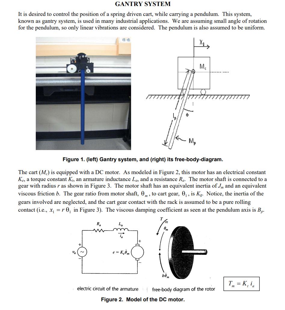
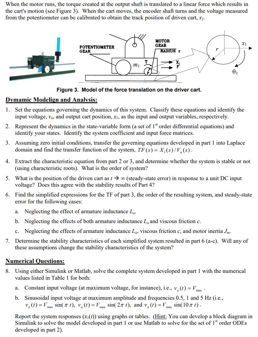
GANTRY SYSTEM It is desired to control the position of a spring driven cart, while carrying...
Fantastic news! We've Found the answer you've been seeking!
Question:
Transcribed Image Text:
GANTRY SYSTEM It is desired to control the position of a spring driven cart, while carrying a pendulum. This system, known as gantry system, is used in many industrial applications. We are assuming small angle of rotation for the pendulum, so only linear vibrations are considered. The pendulum is also assumed to be uniform. Mc Mp Figure 1. (left) Gantry system, and (right) its free-body-diagram. The cart (M) is equipped with a DC motor. As modeled in Figure 2, this motor has an electrical constant Ke, a torque constant K, an armature inductance La, and a resistance Ra. The motor shaft is connected to a gear with radius r as shown in Figure 3. The motor shaft has an equivalent inertia of J, and an equivalent viscous friction b. The gear ratio from motor shaft, 0, to cart gear, 0, is Kg. Notice, the inertia of the gears involved are neglected, and the cart gear contact with the rack is assumed to be a pure rolling contact (i.e., x =r0 in Figure 3). The viscous damping coefficient as seen at the pendulum axis is Bp. Ra T Va e = Kom bm Tm = K, ia electric circuit of the armature free-body diagram of the rotor Figure 2. Model of the DC motor. When the motor runs, the torque created at the output shaft is translated to a linear force which results in the cart's motion (see Figure 3). When the cart moves, the encoder shaft turns and the voltage measured from the potentiometer can be calibrated to obtain the track position of driven cart, x2. POTENTIOMETER GEAR T m MOTOR GEAR RADIUS r 01 x1 Figure 3. Model of the force translation on the driver cart. Dymamic Modelign and Analysis: 1. Set the equations governing the dynamics of this system. Classify these equations and identify the input voltage, va, and output cart position, x1, as the input and output variables, respectively. 2. Represent the dynamics in the state-variable form (a set of 1st order differential equations) and identify your states. Identify the system coefficient and input force matrices. 3. Assuming zero initial conditions, transfer the governing equations developed in part 1 into Laplace domain and find the transfer function of the system, TF (s) = X(s)/V(s). 4. Extract the characteristic equation from part 2 or 3, and determine whether the system is stable or not (using characteristic roots). What is the order of system? 5. What is the position of the driven cart as t (steady-state error) in response to a unit DC input voltage? Does this agree with the stability results of Part 4? 6. Find the simplified expressions for the TF of part 3, the order of the resulting system, and steady-state error for the following cases: a. Neglecting the effect of armature inductance La. b. Neglecting the effects of both armature inductance L, and viscous friction c. c. Neglecting the effects of armature inductance La, viscous friction c, and motor inertia J. 7. Determine the stability characteristics of each simplified system resulted in part 6 (a-c). Will any of these assumptions change the stability characteristics of the system? Numerical Questions: 8. Using either Simulink or Matlab, solve the complete system developed in part 1 with the numerical values listed in Table 1 for both: a. Constant input voltage (at maximum voltage, for instance), i.e., v(t) = V max * b. Sinusoidal input voltage at maximum amplitude and frequencies 0.5, 1 and 5 Hz (i.e., Va(t) = Vmax sin(t), va(t) = Vmax sin(2x t), and v (t) = Vmax sin(10t). Report the system responses (x1(t)) using graphs or tables. (Hint: You can develop a block diagram in Simulink to solve the model developed in part 1 or use Matlab to solve for the set of 1st order ODEs developed in part 2). GANTRY SYSTEM It is desired to control the position of a spring driven cart, while carrying a pendulum. This system, known as gantry system, is used in many industrial applications. We are assuming small angle of rotation for the pendulum, so only linear vibrations are considered. The pendulum is also assumed to be uniform. Mc Mp Figure 1. (left) Gantry system, and (right) its free-body-diagram. The cart (M) is equipped with a DC motor. As modeled in Figure 2, this motor has an electrical constant Ke, a torque constant K, an armature inductance La, and a resistance Ra. The motor shaft is connected to a gear with radius r as shown in Figure 3. The motor shaft has an equivalent inertia of J, and an equivalent viscous friction b. The gear ratio from motor shaft, 0, to cart gear, 0, is Kg. Notice, the inertia of the gears involved are neglected, and the cart gear contact with the rack is assumed to be a pure rolling contact (i.e., x =r0 in Figure 3). The viscous damping coefficient as seen at the pendulum axis is Bp. Ra T Va e = Kom bm Tm = K, ia electric circuit of the armature free-body diagram of the rotor Figure 2. Model of the DC motor. When the motor runs, the torque created at the output shaft is translated to a linear force which results in the cart's motion (see Figure 3). When the cart moves, the encoder shaft turns and the voltage measured from the potentiometer can be calibrated to obtain the track position of driven cart, x2. POTENTIOMETER GEAR T m MOTOR GEAR RADIUS r 01 x1 Figure 3. Model of the force translation on the driver cart. Dymamic Modelign and Analysis: 1. Set the equations governing the dynamics of this system. Classify these equations and identify the input voltage, va, and output cart position, x1, as the input and output variables, respectively. 2. Represent the dynamics in the state-variable form (a set of 1st order differential equations) and identify your states. Identify the system coefficient and input force matrices. 3. Assuming zero initial conditions, transfer the governing equations developed in part 1 into Laplace domain and find the transfer function of the system, TF (s) = X(s)/V(s). 4. Extract the characteristic equation from part 2 or 3, and determine whether the system is stable or not (using characteristic roots). What is the order of system? 5. What is the position of the driven cart as t (steady-state error) in response to a unit DC input voltage? Does this agree with the stability results of Part 4? 6. Find the simplified expressions for the TF of part 3, the order of the resulting system, and steady-state error for the following cases: a. Neglecting the effect of armature inductance La. b. Neglecting the effects of both armature inductance L, and viscous friction c. c. Neglecting the effects of armature inductance La, viscous friction c, and motor inertia J. 7. Determine the stability characteristics of each simplified system resulted in part 6 (a-c). Will any of these assumptions change the stability characteristics of the system? Numerical Questions: 8. Using either Simulink or Matlab, solve the complete system developed in part 1 with the numerical values listed in Table 1 for both: a. Constant input voltage (at maximum voltage, for instance), i.e., v(t) = V max * b. Sinusoidal input voltage at maximum amplitude and frequencies 0.5, 1 and 5 Hz (i.e., Va(t) = Vmax sin(t), va(t) = Vmax sin(2x t), and v (t) = Vmax sin(10t). Report the system responses (x1(t)) using graphs or tables. (Hint: You can develop a block diagram in Simulink to solve the model developed in part 1 or use Matlab to solve for the set of 1st order ODEs developed in part 2).
Expert Answer:
Related Book For
Posted Date:
Students also viewed these mechanical engineering questions
-
inary Differential Equations > Assessment 10.1-10.2 Score: 0.25/3 1/3 answered "X" Question 2 < Submit Question > Gradebook Convert the differential equation `u" -3 u' -4 u = e^(-t)` into a system of...
-
What factors must the auditor consider when determining whether the financial statements are presented in conformity with generally accepted accounting principles?
-
MAC Industries completed the following inventory transactions during the month of August: Requirements 1. Without resorting to calculations, determine which inventory method will result in MAC...
-
Consider the alternative of replacing the rental personnel from the business process in Figure 3-13. a. Describe the changes that will need to be made to the process documented in Figure 3-13.You can...
-
A given bank has the following interest sensitive assets and liabilities on its balance sheet ( in million Kwacha ) . Interest Rate Sensitive Assets Interest Rate Sensitive Liabilities Government...
-
You have a 6-year-old bilingual second language learner on your caseload who has an IEP. He was diagnosed as speech/language impaired by a previous therapist, and has goals to work on: increasing...
-
Akiak Nori was raised in Arviat, Nunavut, and then attended a career school in Thunder Bay, Ontario, majoring in electronic technology. Approaching graduation, he sorted through dozens of job offers...
-
1) Microsoft Outlook 2) Microsoft Teams 3) Whatsapp/Phone massager 4) Google Gmail 5) Google Meet 6) Google Chat and many more with above mentioned, how employees use digital communication to...
-
Given our focus on message processing, I believe it would be valuable to try applying the elaboration likelihood model (ELM) and/or the heuristic systematic model (HSM) to evaluate the goals of...
-
4 (B) On 1st January 2023, an investor has portfolio of Rs 1 Crore with a portfolio beta of 0.8. while the prices of nifty spot and nifty future are shown below: Stock Nifty spot Nifty July Futures...
-
Assume that the City of Coyote has produced its financial statements for December 31, 2024, and the year then ended. The city's general fund was only used to monitor education and parks. Its capital...
Study smarter with the SolutionInn App