Question: Given: Only the information in the Case Study below Derive: State Machine Diagram (Hand-drawn) Submit: Your work using the text area or the add file
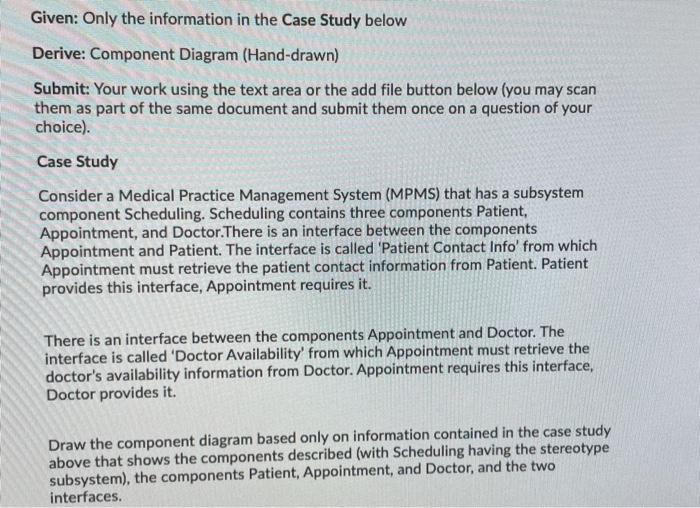
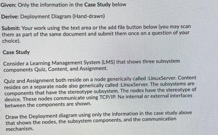
Given: Only the information in the Case Study below Derive: State Machine Diagram (Hand-drawn) Submit: Your work using the text area or the add file button below (you may scan them as part of the same document and submit them once on a question of your choice). Case Study Consider a Medical Practice Management System (MPMS) that provides managing patient Appointments in the system. The time of the appointment must fit the availability of both the patient and the doctor. Once a time is found that fits, then the appointment becomes 'Scheduled'. If the appointment time arrives and the patient does not cancel the appointment and does not arrive for the appointment, then the appointment becomes 'Missed'. If either the patient or the doctor cannot make the scheduled time, then the appointment becomes 'Cancelled. If both the patient and the doctor meet as planned, then the appointment becomes 'Complete. We can assume that the first state of an appointment after entering our system is 'Scheduled'. An appointment can only become 'Missed. Cancelled' or 'Complete following the 'Scheduled' state. The last state before leaving the system can only be 'Missed, 'Cancelled', or 'Complete Create a State Machine diagram based only on the information in this Case Study that shows the states of the Appointment object in the life cycle: Scheduled, Missed, Cancelled, and Complete. Label all transitions from one state to another. The diagram must include the initial Start State as the Appointment enters the system and the Stop State after the Appointment leaves the system (shown below for clarification) Initial Start State Stop State Given: Only the information in the Case Study below Derive: Component Diagram (Hand-drawn) Submit: Your work using the text area or the add file button below (you may scan them as part of the same document and submit them once on a question of your choice). Case Study Consider a Medical Practice Management System (MPMS) that has a subsystem component Scheduling. Scheduling contains three components Patient, Appointment, and Doctor.There is an interface between the components Appointment and Patient. The interface is called 'Patient Contact Info' from which Appointment must retrieve the patient contact information from Patient. Patient provides this interface, Appointment requires it. There is an interface between the components Appointment and Doctor. The interface is called 'Doctor Availability' from which Appointment must retrieve the doctor's availability information from Doctor. Appointment requires this interface, Doctor provides it. Draw the component diagram based only on information contained in the case study above that shows the components described (with Scheduling having the stereotype subsystem), the components Patient, Appointment, and Doctor, and the two interfaces. Given: Only the information in the Case Study below Derive: Deployment Diagram (Hand-drawn) Submit: Your work using the text area or the add file button below (you may scan them as part of the same document and submit them once on a question of your choice). Case Study Consider a Learning Management System (LMS) that shows three subsystem components Quiz, Content, and Assignment. Quiz and Assignment both reside on a node generically called :LinuxServer. Content resides on a separate node also generically called :Linux Server. The subsystems are components that have the stereotype subsystem. The nodes have the stereotype of device. These nodes communicate using TCP/IP. No internal or external interfaces between the components are shown. Draw the Deployment diagram using only the information in the case study above that shows the nodes, the subsystem components, and the communication mechanism. Given: Only the information in the Case Study below Derive: State Machine Diagram (Hand-drawn) Submit: Your work using the text area or the add file button below (you may scan them as part of the same document and submit them once on a question of your choice). Case Study Consider a Medical Practice Management System (MPMS) that provides managing patient Appointments in the system. The time of the appointment must fit the availability of both the patient and the doctor. Once a time is found that fits, then the appointment becomes 'Scheduled'. If the appointment time arrives and the patient does not cancel the appointment and does not arrive for the appointment, then the appointment becomes 'Missed'. If either the patient or the doctor cannot make the scheduled time, then the appointment becomes 'Cancelled. If both the patient and the doctor meet as planned, then the appointment becomes 'Complete. We can assume that the first state of an appointment after entering our system is 'Scheduled'. An appointment can only become 'Missed. Cancelled' or 'Complete following the 'Scheduled' state. The last state before leaving the system can only be 'Missed, 'Cancelled', or 'Complete Create a State Machine diagram based only on the information in this Case Study that shows the states of the Appointment object in the life cycle: Scheduled, Missed, Cancelled, and Complete. Label all transitions from one state to another. The diagram must include the initial Start State as the Appointment enters the system and the Stop State after the Appointment leaves the system (shown below for clarification) Initial Start State Stop State Given: Only the information in the Case Study below Derive: Component Diagram (Hand-drawn) Submit: Your work using the text area or the add file button below (you may scan them as part of the same document and submit them once on a question of your choice). Case Study Consider a Medical Practice Management System (MPMS) that has a subsystem component Scheduling. Scheduling contains three components Patient, Appointment, and Doctor.There is an interface between the components Appointment and Patient. The interface is called 'Patient Contact Info' from which Appointment must retrieve the patient contact information from Patient. Patient provides this interface, Appointment requires it. There is an interface between the components Appointment and Doctor. The interface is called 'Doctor Availability' from which Appointment must retrieve the doctor's availability information from Doctor. Appointment requires this interface, Doctor provides it. Draw the component diagram based only on information contained in the case study above that shows the components described (with Scheduling having the stereotype subsystem), the components Patient, Appointment, and Doctor, and the two interfaces. Given: Only the information in the Case Study below Derive: Deployment Diagram (Hand-drawn) Submit: Your work using the text area or the add file button below (you may scan them as part of the same document and submit them once on a question of your choice). Case Study Consider a Learning Management System (LMS) that shows three subsystem components Quiz, Content, and Assignment. Quiz and Assignment both reside on a node generically called :LinuxServer. Content resides on a separate node also generically called :Linux Server. The subsystems are components that have the stereotype subsystem. The nodes have the stereotype of device. These nodes communicate using TCP/IP. No internal or external interfaces between the components are shown. Draw the Deployment diagram using only the information in the case study above that shows the nodes, the subsystem components, and the communication mechanism