

Question: Gray Code Consider a 4 - bit binary counter currently storing the decimal number 7 ; its internal binary representation is 0 1 1 1
Gray Code
Consider a bit binary counter currently storing the decimal number ; its internal binary representation is When the count rolls over to the internal bits become requiring all bits to switch simultaneously. Although numbers and have a distance of between them, the binary representations bear little resemblance to each other. This phenomenon extends to nbits: whenever the number rolls over from n to n n bits must change state at once. In electronics, current is drawn whenever a bit transitions from low to high or vice versa; however, power consumption is minimized when the state of each bit is preserved. Consequently, it might be desirable to develop a design that minimizes the amount of bit flips during a counter operation. Furthermore, numerous simultaneous bit flips can introduce errors into the circuit.
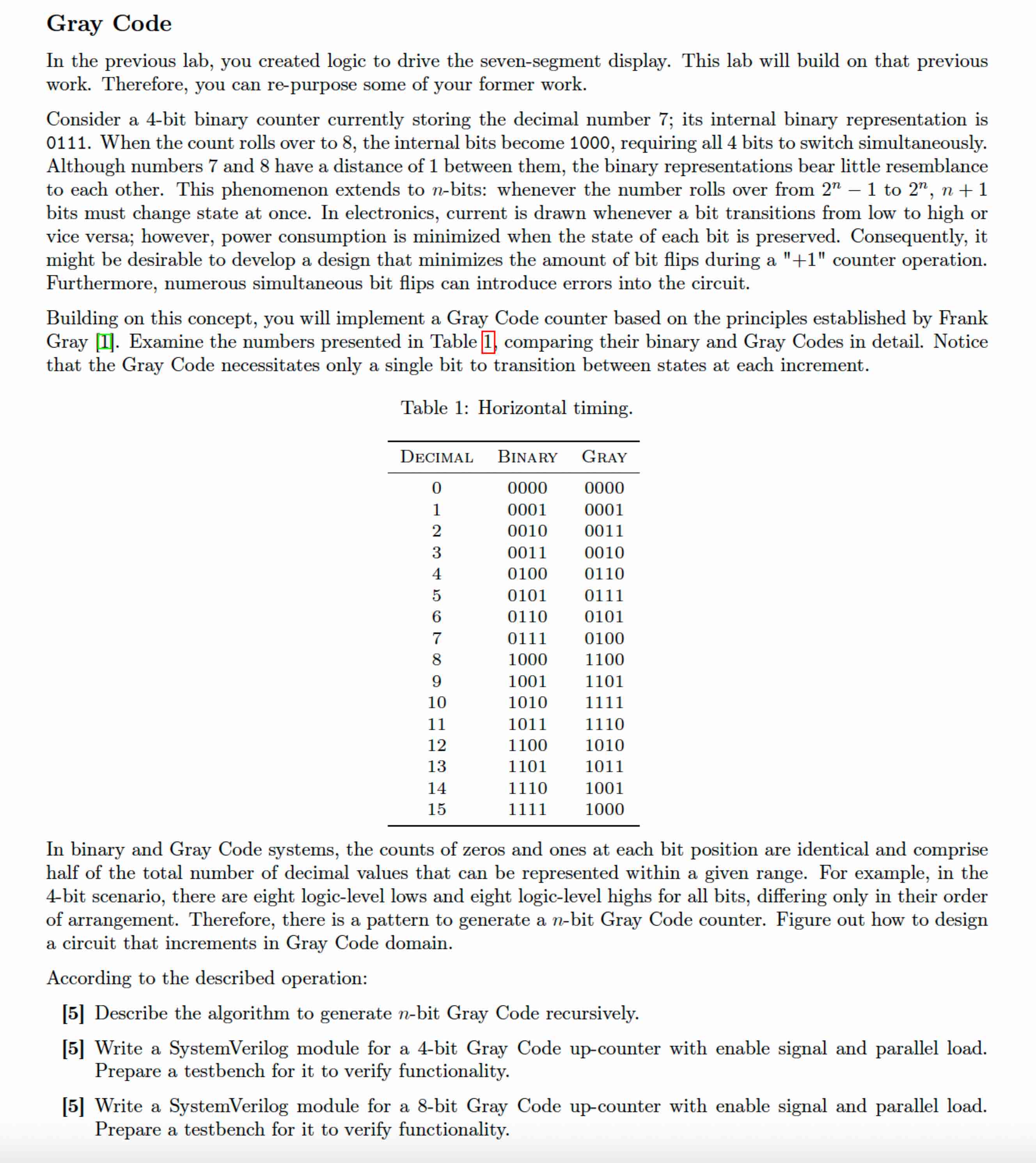
Building on this concept, you will implement a Gray Code counter based on the principles established by Frank Gray Examine the numbers presented in Table comparing their binary and Gray Codes in detail. Notice that the Gray Code necessitates only a single bit to transition between states at each increment.
In binary and Gray Code systems, the counts of zeros and ones at each bit position are identical and comprise half of the total number of decimal values that can be represented within a given range. For example, in the bit scenario, there are eight logiclevel lows and eight logiclevel highs for all bits, differing only in their order of arrangement. Therefore, there is a pattern to generate a nbit Gray Code counter. Figure out how to design a circuit that increments in Gray Code domain.
According to the described operation:
Describe the algorithm to generate nbit Gray Code recursively.
Write a SystemVerilog module for a bit Gray Code upcounter with enable signal and parallel load. Prepare a testbench for it to verify functionality.
Write a SystemVerilog module for a bit Gray Code upcounter with enable signal and parallel load. Prepare a testbench for it to verify functionality.
Step by Step Solution
There are 3 Steps involved in it
1 Expert Approved Answer
Step: 1 Unlock

Question Has Been Solved by an Expert!
Get step-by-step solutions from verified subject matter experts
Step: 2 Unlock
Step: 3 Unlock