

Question: Question 1 ( 2 0 Marks ) A synchronous boost converter is shown in Fig. 1 . The switches T 1 and T 2 operate
Question Marks
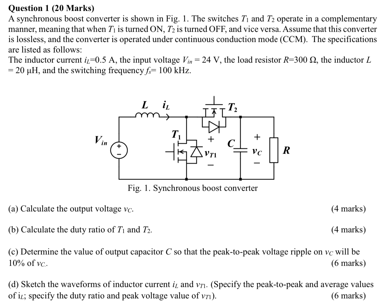
A synchronous boost converter is shown in Fig. The switches and operate in a complementary manner, meaning that when is turned is turned OFF and vice versa. Assume that this converter is lossless, and the converter is operated under continuous conduction mode CCM The specifications are listed as follows:
The inductor current the input voltage the load resistor the inductor and the switching frequency
rig. syillimuilius unust culiveiter
a Calculate the output voltage
marks
b Calculate the duty ratio of and
marks
c Determine the value of output capacitor so that the peaktopeak voltage ripple on will be of
marks
d Sketch the waveforms of inductor current and Specify the peaktopeak and average values of ; specify the duty ratio and peak voltage value of
marks
Step by Step Solution
There are 3 Steps involved in it
1 Expert Approved Answer
Step: 1 Unlock

Question Has Been Solved by an Expert!
Get step-by-step solutions from verified subject matter experts
Step: 2 Unlock
Step: 3 Unlock