

Question: Hand written solution required Advanced Physics The circular shaft shown [Figu re 2) has dimensions d1 = 21.5 cm , L1 = 6 mm ,
Hand written solution required
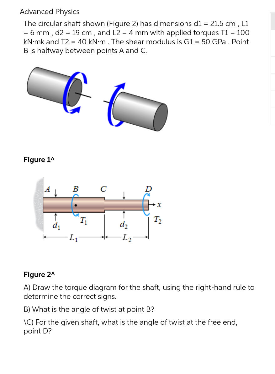
Advanced Physics The circular shaft shown [Figu re 2) has dimensions d1 = 21.5 cm , L1 = 6 mm , d2 = 19 cm , and L2 = 4 mm with applied torques T1 = 100 kN-mk and T2 = 40 kN-m . The shear modulus is G]. = 50 GPa. Point B is halfway between points A and C. Figure 1" Figure 2\" A} Draw the torque diagram for the shaft, using the right-hand rule to determine the correct signs. B) What is the angle of twist at point B? \\C} For the given shaft, what is the angle of twist at the free end, point D
Step by Step Solution
There are 3 Steps involved in it
1 Expert Approved Answer
Step: 1 Unlock

Question Has Been Solved by an Expert!
Get step-by-step solutions from verified subject matter experts
Step: 2 Unlock
Step: 3 Unlock