

Question: Bevel gears transmit torsional, bending, and axial loads to rotating shafts, such as shown in Figure! For this problem, the free body diagram for
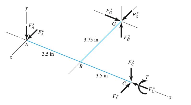
Bevel gears transmit torsional, bending, and axial loads to rotating shafts, such as shown in Figure! For this problem, the free body diagram for a shaft ABC is shown in the figure, where points A and C are at the bearings. Line BG is on the bevel gear extended to the shaft center from point G, the contact point with the mating gear. Transmitted from the mating gear are tangential, radial, and axial forces FG = 500 lbf, F = 58 lbf, and FG = 173 lbf, respectively. The bearing at C supports the axial thrust load. For the shaft material, Su = 90 kpsi, Sy = 65 kpsi, and has a fully corrected endurance limit of 40 kpsi. Let (Kf)a= 2.3, (Kf)b = 2.0, and (Ks)t = 1.5, where the subscripts a, b, and t represent axial, bending, and torsion, respectively. The diameter of shaft ABC is 1.5 in. (a) For the DE-Goodman criterion, develop a general equation for the design factor using Equations (6-46), (666), (667), (7-2), and (7-3); and Fm and Fa for the mean and alternating axial forces, respectively. N y FX A NA 3.5 in B 3.75 in FG 3.5 in G NU FG Fa Fr F X
Step by Step Solution
3.38 Rating (157 Votes )
There are 3 Steps involved in it
Given Tangential force FGy 500 lbf Radial force FGz 58 lbf Axial force FGx 173 lbf Su 90 kpsi Sy 6... View full answer

Get step-by-step solutions from verified subject matter experts