

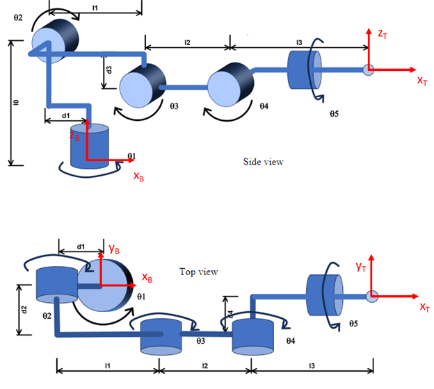
Question: he link length are defined as follows: l 0 = 0 . 3 5 m l 1 = 0 . 2 5 m l 2
he link length are defined as follows: lm lm lm lm
There are displacements between some of the joints: dm dm dm dm
The picture above shows the robot in the configuration where all joint angles are The direction of
positive rotation is shown about each joint.
The simulator will actually show one additional joint joint corresponding to the opening of the gripper.
This, however, is not relevant for the kinematic functions and can be ignored
You are to derive and implement a partial inverse kinematic solution for the robot manipulator. To make
this problem tractable, we assume theta and require that the Xaxis of the tool frame is pointed straight
down
Step by Step Solution
There are 3 Steps involved in it
1 Expert Approved Answer
Step: 1 Unlock

Question Has Been Solved by an Expert!
Get step-by-step solutions from verified subject matter experts
Step: 2 Unlock
Step: 3 Unlock