

Question: Hello! I require you to - describe the circuit - draw the circuit ( do not copy and paste the circuit ) . Use Circuit
Hello! I require you to
describe the circuit
draw the circuit do not copy and paste the circuit Use Circuit Cad to draw the circuit.
label the components properly, R R Ufor IC plus a legend what the IC is Q QBJT transistor Ddiode Ccapacitor Krelays etc.
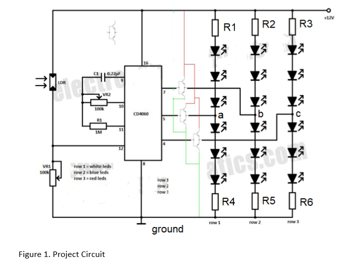
Below is a description of the circuit and the circuit itself.
Figure Project CircuitThe circuit is a simple blinker circuit controlled by the binary counter CD Nodes a b and c are the points of connection to the output of the CD When the output of the counter is low V the upper LEDs between the supply and the nodes is activated while when the output is high Vcc the lower LEDs are activated below the nodes The use of the complementary pair increases the current drive and also inverts the signal of the counter, that is when the counter is low, the pnp turns on pulling the lower LEDs to Vcc while the upper LEDs are turned off.
For the complementary pair, you may use N and N
Step by Step Solution
There are 3 Steps involved in it
1 Expert Approved Answer
Step: 1 Unlock

Question Has Been Solved by an Expert!
Get step-by-step solutions from verified subject matter experts
Step: 2 Unlock
Step: 3 Unlock