

Question: Hello, Would please show me steps by steps with this question. Figure Q6 (a) and (b) show the arrangement of keys and the circuit diagram
Hello, Would please show me steps by steps with this question.
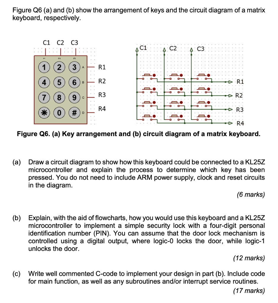
Figure Q6 (a) and (b) show the arrangement of keys and the circuit diagram of a matrix keyboard, respectively. Figure Q6. (a) Key arrangement and (b) circuit diagram of a matrix keyboard. (a) Draw a circuit diagram to show how this keyboard could be connected to a KL25Z microcontroller and explain the process to determine which key has been pressed. You do not need to include ARM power supply, clock and reset circuits in the diagram. (6 marks) (b) Explain, with the aid of flowcharts, how you would use this keyboard and a KL25Z microcontroller to implement a simple security lock with a four-digit personal identification number (PIN). You can assume that the door lock mechanism is controlled using a digital output, where logic-0 locks the door, while logic-1 unlocks the door. (12 marks) (c) Write well commented C-code to implement your design in part (b). Include code for main function, as well as any subroutines and/or interrupt service routines. (17 marks)
Step by Step Solution
There are 3 Steps involved in it

Get step-by-step solutions from verified subject matter experts