

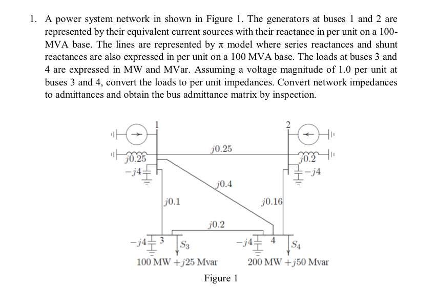
Question: help 1 . A power system network in shown in Figure 1 . The generators at buses 1 and 2 are represented by their equivalent
help A power system network in shown in Figure The generators at buses and are represented by their equivalent current sources with their reactance in per unit on a MVA base. The lines are represented by pi model where series reactances and shunt reactances are also expressed in per unit on a MVA base. The loads at buses and are expressed in MW and MVar. Assuming a voltage magnitude of per unit at buses and convert the loads to per unit impedances. Convert network impedances to admittances and obtain the bus admittance matrix by inspection.
Step by Step Solution
There are 3 Steps involved in it
1 Expert Approved Answer
Step: 1 Unlock

Question Has Been Solved by an Expert!
Get step-by-step solutions from verified subject matter experts
Step: 2 Unlock
Step: 3 Unlock