

Question: 6.1. A power system network is shown in Figure 6.17. The generators at buses 1 and 2 are represented by their equivalent current sources
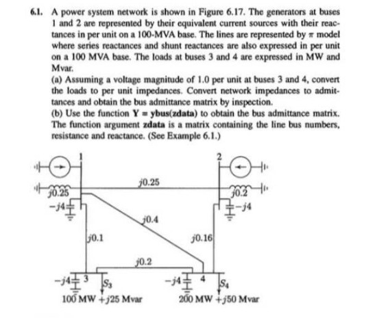
6.1. A power system network is shown in Figure 6.17. The generators at buses 1 and 2 are represented by their equivalent current sources with their reac- tances in per unit on a 100-MVA base. The lines are represented by a model where series reactances and shunt reactances are also expressed in per unit on a 100 MVA base. The loads at buses 3 and 4 are expressed in MW and Mvar. (a) Assuming a voltage magnitude of 1.0 per unit at buses 3 and 4, convert the loads to per unit impedances. Convert network impedances to admit- tances and obtain the bus admittance matrix by inspection. (b) Use the function Y=ybus(zdata) to obtain the bus admittance matrix. The function argument zdata is a matrix containing the line bus numbers, resistance and reactance. (See Example 6.1.) 30.25 50.1 j0.25 20.4 j0.2 $3 100 MW +125 Mvar j0.16 30.2 -j4 S4 200 MW +150 Mvar
Step by Step Solution
3.48 Rating (158 Votes )
There are 3 Steps involved in it

Get step-by-step solutions from verified subject matter experts