

Question: help in assembly Given a 4-bit full-adder-based ALU (see diagram), come up with a minimal additional circuit that correctly sets (or clears) the status flags
help in assembly
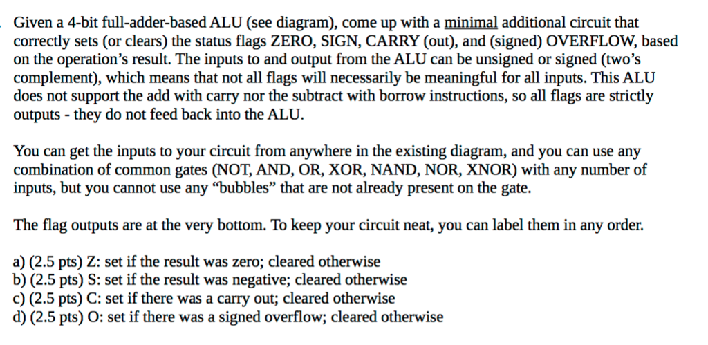
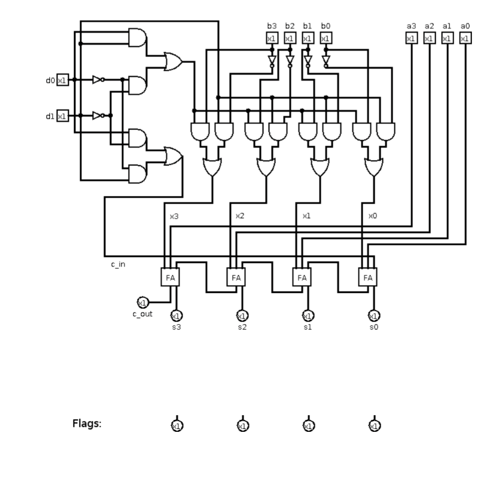
Given a 4-bit full-adder-based ALU (see diagram), come up with a minimal additional circuit that correctly sets (or clears) the status flags ZERO, SIGN, CARRY (out), and (signed) OVERFLOW, based on the operation's result. The inputs to and output from the ALU can be unsigned or signed (two's complement), which means that not all flags will necessarily be meaningful for all inputs. This ALU does not support the add with carry nor the subtract with borrow instructions, so all flags are strictly outputs - they do not feed back into the ALU. You can get the inputs to your circuit from anywhere in the existing diagram, and you can use any combination of common gates (NOT, AND, OR, XOR, NAND, NOR, XNOR) with any number of inputs, but you cannot use any "bubbles" that are not already present on the gate. The flag outputs are at the very bottom. To keep your circuit neat, you can label them in any order. a) (2.5 pts) Z: set if the result was zero; cleared otherwise b) (2.5 pts) S: set if the result was negative; cleared otherwise c) (2.5 pts) C: set if there was a carry d) (2.5 pts) O: set if there was a signed overflow; cleared otherwise out: cleared otherwise Given a 4-bit full-adder-based ALU (see diagram), come up with a minimal additional circuit that correctly sets (or clears) the status flags ZERO, SIGN, CARRY (out), and (signed) OVERFLOW, based on the operation's result. The inputs to and output from the ALU can be unsigned or signed (two's complement), which means that not all flags will necessarily be meaningful for all inputs. This ALU does not support the add with carry nor the subtract with borrow instructions, so all flags are strictly outputs - they do not feed back into the ALU. You can get the inputs to your circuit from anywhere in the existing diagram, and you can use any combination of common gates (NOT, AND, OR, XOR, NAND, NOR, XNOR) with any number of inputs, but you cannot use any "bubbles" that are not already present on the gate. The flag outputs are at the very bottom. To keep your circuit neat, you can label them in any order. a) (2.5 pts) Z: set if the result was zero; cleared otherwise b) (2.5 pts) S: set if the result was negative; cleared otherwise c) (2.5 pts) C: set if there was a carry d) (2.5 pts) O: set if there was a signed overflow; cleared otherwise out: cleared otherwise
Step by Step Solution
There are 3 Steps involved in it

Get step-by-step solutions from verified subject matter experts