

Question: Help please 2. Figure 1 shows the overall system for filtering a CT signal using a DT filter. It is given that 1/T=25kHz, and the
Help please 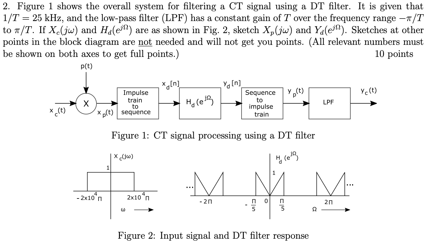
2. Figure 1 shows the overall system for filtering a CT signal using a DT filter. It is given that 1/T=25kHz, and the low-pass filter (LPF) has a constant gain of T over the frequency range /T to /T. If Xc(j) and Hd(ej) are as shown in Fig. 2, sketch Xp(j) and Yd(ej). Sketches at other points in the block diagram are not needed and will not get you points. (All relevant numbers must be shown on both axes to get full points.) 10 points Figure 1: CT signal processing using a DT filter Figure 2: Input signal and DT filter response 2. Figure 1 shows the overall system for filtering a CT signal using a DT filter. It is given that 1/T=25kHz, and the low-pass filter (LPF) has a constant gain of T over the frequency range /T to /T. If Xc(j) and Hd(ej) are as shown in Fig. 2, sketch Xp(j) and Yd(ej). Sketches at other points in the block diagram are not needed and will not get you points. (All relevant numbers must be shown on both axes to get full points.) 10 points Figure 1: CT signal processing using a DT filter Figure 2: Input signal and DT filter response
Step by Step Solution
There are 3 Steps involved in it
It seems that youve referenced figures or images Figure 1 and Figure 2 in your question but I cant view or analyze images directly However I can guide ... View full answer

Get step-by-step solutions from verified subject matter experts