

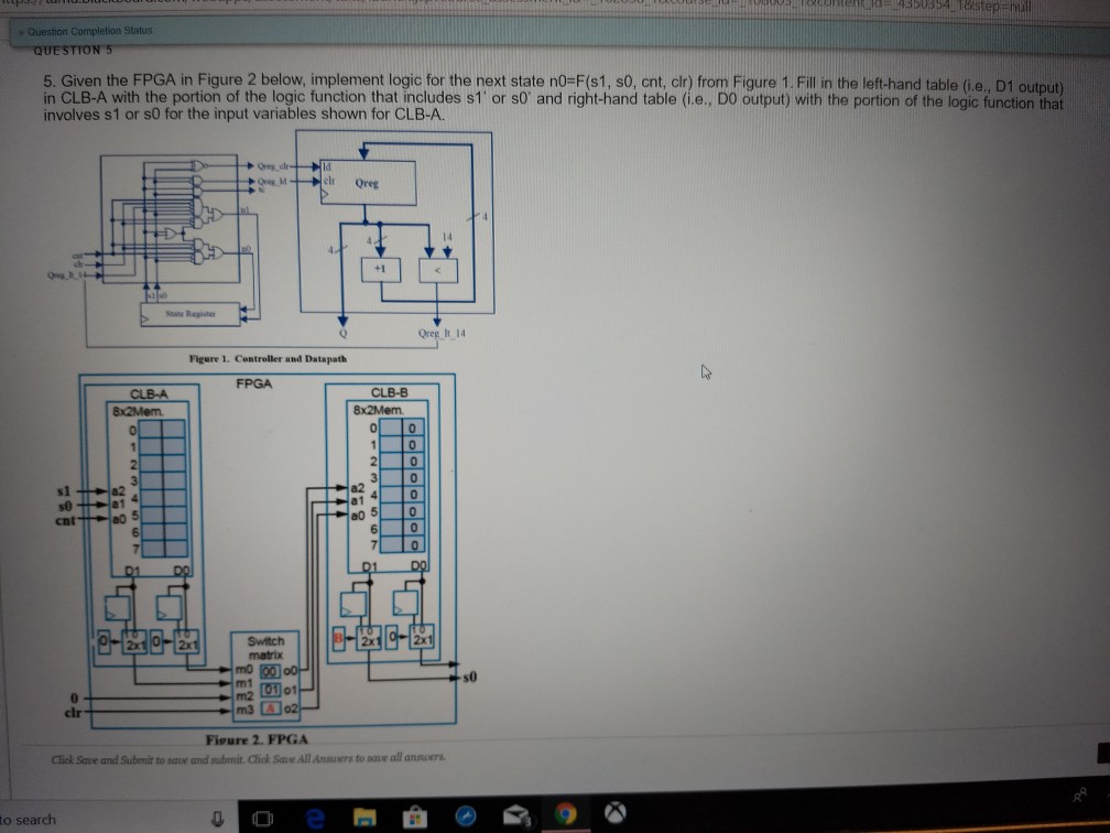
Question: Help please! - Question Completion Status 5. Given the FPGA in Figure 2 below, implement logic for the next state nO-F(s1, s0, cnt, clr) from
Help please!
- Question Completion Status 5. Given the FPGA in Figure 2 below, implement logic for the next state nO-F(s1, s0, cnt, clr) from Figure 1. Fill n the left-hand table (i.e., D1 output) in CLB-A with the portion of the logic function that includes s1' or s0 and right-hand table (i.e., DO output) with the portion of the logic function that involves s1 or s0 for the input variables shown for CLB-A. ld clr Qreg +1 Sate Register Oreg It 14 Figure 1. Centroller and Datapath FPGA CLB-B 01-10 s1 00 5 0 6 7 Switch matrix s0 Figure 2-FPGA Click Sase and Submit to saue and submit. Click SaeAnAnsuers to saue all ansuer to search - Question Completion Status 5. Given the FPGA in Figure 2 below, implement logic for the next state nO-F(s1, s0, cnt, clr) from Figure 1. Fill n the left-hand table (i.e., D1 output) in CLB-A with the portion of the logic function that includes s1' or s0 and right-hand table (i.e., DO output) with the portion of the logic function that involves s1 or s0 for the input variables shown for CLB-A. ld clr Qreg +1 Sate Register Oreg It 14 Figure 1. Centroller and Datapath FPGA CLB-B 01-10 s1 00 5 0 6 7 Switch matrix s0 Figure 2-FPGA Click Sase and Submit to saue and submit. Click SaeAnAnsuers to saue all ansuer to search
Step by Step Solution
There are 3 Steps involved in it

Get step-by-step solutions from verified subject matter experts