

Question: help Step 2 . Turn on the power supply and apply a clock frequency of 1 0 kHz to the cascaded counters. Apply 1 0
help
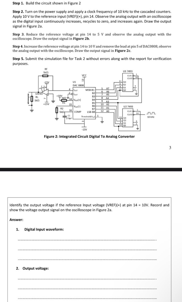
Step Turn on the power supply and apply a clock frequency of kHz to the cascaded counters. Apply V to the reference input VREF pin Observe the analog output with an oscilloscope as the digital input continuously increases, recycles to zero, and increases again. Draw the output signal in Figure a
Step Reduce the reference voltage at pin to V and observe the analog output with the oscilloscope. Draw the output signal in Figure b
Step Increase the reference voltage at pin to V and remove the lead at pin of DAC observe the analog output with the oscilloscope. Draw the output signal in Figure c
Step Submit the simulation file for Task without errors along with the report for verification purposes.
Identify the output voltage if the reference Input voltage VREF at pin mathrm~V Record and show the voltage output signal on the oscilloscope in Figure a
Answer:
Digital Input waveform:
Output voltage:
Step by Step Solution
There are 3 Steps involved in it
1 Expert Approved Answer
Step: 1 Unlock

Question Has Been Solved by an Expert!
Get step-by-step solutions from verified subject matter experts
Step: 2 Unlock
Step: 3 Unlock