

Question: heres my code again: module lab7 ( input logic reset_n, clk_in, clk_50, output logic [2:0] en, output logic a,b,c,d,e,f,g ); logic clk; logic [2:0] count,
![clk_50, output logic [2:0] en, output logic a,b,c,d,e,f,g ); logic clk; logic](https://dsd5zvtm8ll6.cloudfront.net/si.experts.images/questions/2024/09/66f32185d905e_86166f32185bc367.jpg)
![[2:0] count, count_next ; debounce debounce0 (clk_in, clk_50, clk) ; always_ff@(posedge clk)](https://dsd5zvtm8ll6.cloudfront.net/si.experts.images/questions/2024/09/66f321869fb8d_86266f3218615767.jpg)
heres my code again:
module lab7
(
input logic reset_n, clk_in, clk_50,
output logic [2:0] en,
output logic a,b,c,d,e,f,g
);
logic clk;
logic [2:0] count, count_next ;
debounce debounce0 (clk_in, clk_50, clk) ;
always_ff@(posedge clk) count = count_next ;
assign {en, a,b,c,d,e,f,g } = count == 3'b000 ? {4'b1000,7'h01} : count == 3'b001 ? {4'b1000,7'h01} : count == 3'b010 ? {4'b0100,7'h01} : count == 3'b011 ? {4'b0010,7'h04} : count == 3'b100 ? {4'b0001,7'h00} : count == 3'b101 ? {4'b1000,7'h01} : count == 3'b110 ? {4'b0100,7'h00} : count == 3'b111 ? {4'b0010,7'h20} : {4'b0001,7'h04} ;always_comb
if (reset_n == 0)
count_next = 0 ;
else
if( count == 8 )
count_next = 0 ;
else
count_next = count + 1'b1;
endmodule
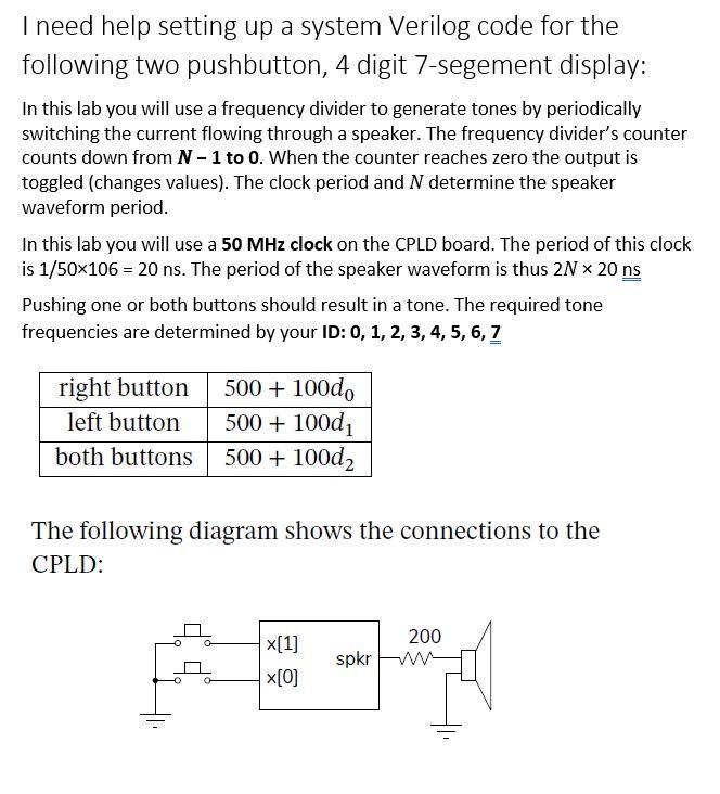
I need help setting up a system Verilog code for the following two pushbutton, 4 digit 7-segement display: In this lab you will use a frequency divider to generate tones by periodically switching the current flowing through a speaker. The frequency divider's counter counts down from N - 1 to 0. When the counter reaches zero the output is toggled (changes values). The clock period and N determine the speaker waveform period. In this lab you will use a 50 MHz clock on the CPLD board. The period of this clock is 1/50x106 = 20 ns. The period of the speaker waveform is thus 2N 20 ns Pushing one or both buttons should result in a tone. The required tone frequencies are determined by your ID: 0, 1, 2, 3, 4, 5, 6, 7 right button left button both buttons 500 + 100d, 500 + 10001 500 + 100d2 The following diagram shows the connections to the CPLD: x[1] x[0] 200 W spkr Sample Design If no button is being pushed the counter is set to 1. Otherwise if the counter is non-zero, the counter is decremented, otherwise it's loaded with a value equal to the appropriate number of clock cycles for a half period. The speaker output is toggled (changed to the op- posite value) when the count is zero. This results in a speaker waveform that is square wave with the re- quired period. I need help implementing the speakers with my system Verilog code: module lab7 = == == ( input logic reset_n, clk_in, clk_50, output logic (2:0) en, output logic a,b,c,d,e,f,g ); logic clk; logic (2:0) count, count next ; debounce debouncel (clk_in, clk_50, clk); always_ff@(posedge clk) count = count_next ; assign {en, a,b,c,d,e,f,g} count 3'000 ? {4'b1000,7'h01}; count 3'b001 ? {4'b1000,7'h01) : count 3'b010 ? {4'b0100,7'h01} : count 3'b011 ? {4'b0010,7'h04} : count == 3'b100 ? {4'50001,7'h00}: count 3'b101 ? {4'b1000,7'h01) : count 3'b110 ? {4'b0100,7'h00} : count 3'b111 ? {4'b0010,7'h20}: {4'b0001,7'h04}; always_comb if (reset_n 0) count_next else if( count 8) count_next = 0; else count_next count + 1'61; endmodule == == == == == I need help setting up a system Verilog code for the following two pushbutton, 4 digit 7-segement display: In this lab you will use a frequency divider to generate tones by periodically switching the current flowing through a speaker. The frequency divider's counter counts down from N - 1 to 0. When the counter reaches zero the output is toggled (changes values). The clock period and N determine the speaker waveform period. In this lab you will use a 50 MHz clock on the CPLD board. The period of this clock is 1/50x106 = 20 ns. The period of the speaker waveform is thus 2N 20 ns Pushing one or both buttons should result in a tone. The required tone frequencies are determined by your ID: 0, 1, 2, 3, 4, 5, 6, 7 right button left button both buttons 500 + 100d, 500 + 10001 500 + 100d2 The following diagram shows the connections to the CPLD: x[1] x[0] 200 W spkr Sample Design If no button is being pushed the counter is set to 1. Otherwise if the counter is non-zero, the counter is decremented, otherwise it's loaded with a value equal to the appropriate number of clock cycles for a half period. The speaker output is toggled (changed to the op- posite value) when the count is zero. This results in a speaker waveform that is square wave with the re- quired period. I need help implementing the speakers with my system Verilog code: module lab7 = == == ( input logic reset_n, clk_in, clk_50, output logic (2:0) en, output logic a,b,c,d,e,f,g ); logic clk; logic (2:0) count, count next ; debounce debouncel (clk_in, clk_50, clk); always_ff@(posedge clk) count = count_next ; assign {en, a,b,c,d,e,f,g} count 3'000 ? {4'b1000,7'h01}; count 3'b001 ? {4'b1000,7'h01) : count 3'b010 ? {4'b0100,7'h01} : count 3'b011 ? {4'b0010,7'h04} : count == 3'b100 ? {4'50001,7'h00}: count 3'b101 ? {4'b1000,7'h01) : count 3'b110 ? {4'b0100,7'h00} : count 3'b111 ? {4'b0010,7'h20}: {4'b0001,7'h04}; always_comb if (reset_n 0) count_next else if( count 8) count_next = 0; else count_next count + 1'61; endmodule == == == == ==
Step by Step Solution
There are 3 Steps involved in it

Get step-by-step solutions from verified subject matter experts