

Question: Hi ! I ' m going to share a Proteus image. In this image, in the left bottom R 5 and R 3 used for
Hi Im going to share a Proteus image. In this image, in the left bottom
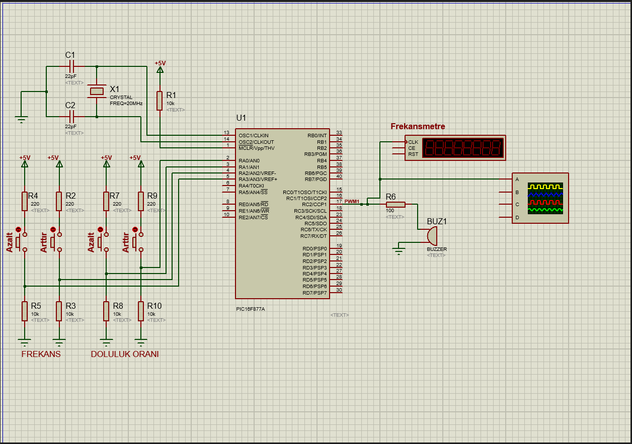
R and R used for frequency. R is for decrease and R is for increase.
R and R used for duty cycle. R is for decrease and R is for increase.
This was for introduction in my set. Now Im going to share you details about my project;
Write and run a PWM application that starts operating at a duty cycle and Hz frequency when executed. It should be possible to increase or decrease the duty cycle by increments with two buttons, and to increase or decrease the PWM frequency by Hz increments with another two buttons. Use the RC pin as the output pin to observe through a buzzer and frequency meter.ject.
Step by Step Solution
There are 3 Steps involved in it
1 Expert Approved Answer
Step: 1 Unlock

Question Has Been Solved by an Expert!
Get step-by-step solutions from verified subject matter experts
Step: 2 Unlock
Step: 3 Unlock