

Question: How do I work out the Bending Moment here? I've managed to solve the reactions in each 2 supports, and SF and BM from the
How do I work out the Bending Moment here? I've managed to solve the reactions in each supports, and SF and BM from the st support left side But I can't seem to get the BMkNm or anywhere near it Im not sure why...
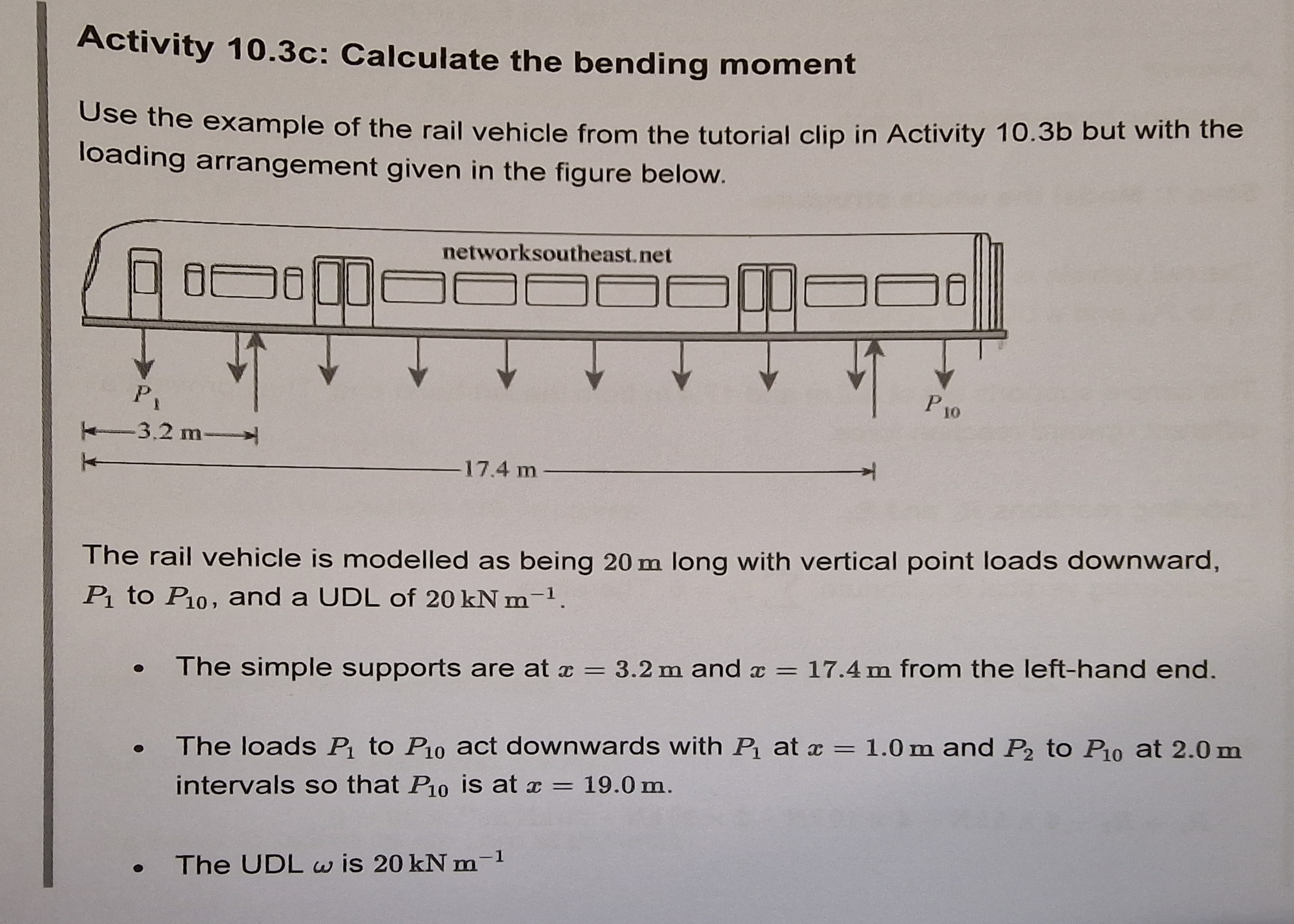
Activity c: Calculate the bending moment
Use the example of the rail vehicle from the tutorial clip in Activity but with the
loading arrangement given in the figure below.
The rail vehicle is modelled as being long with vertical point loads downward,
to and a UDL of
The simple supports are at and from the lefthand end.
The loads to act downwards with at and to at
intervals so that is at
The UDL is
and are
and are
and are
and are
and are
and act at from either end of the vehicle and the other point
loads act at intervals of between and
Show that the bending moment at the centre of the vehicle is and that the
maximum bending moment is to the nearest
The shear force will increase linearly with the distributed load and vertically up with
each point load and then decrease at each support.
The bending moment will change as a parabola before changing direction at the
support, reaching a maximum near the centre and finally changing direction again
at the next support.
Step : Draw the SF and BM diagrams
Take a piece of squared graph paper and draw a scale version of the rail vehicle.
Add the axes for both the SF and BM diagrams. Calculate the shear forces and
bending moments at the key points of the supports.
Starting with the vehicle up to the lefthand support, the only forces acting on this
part of the beam are two point loads and : and the UDL of that portion of the
vehicle as shown below.
Now, repeating the step directly above to calculate and at the righthand
support, the only forces acting on this part of the beam are ten point loads to
P to and the UDL of that portion of the vehicle gives
and
kNmActivity c: Calculate the bending moment
Use the example of the rail vehicle from the tutorial clip in Activity but with the
loading arrangement given in the figure below.
The rail vehicle is modelled as being long with vertical point loads downward,
to and a UDL of
The simple supports are at and from the lefthand end.
The loads to act downwards with at and to at
intervals so that is at
The UDL is
Step by Step Solution
There are 3 Steps involved in it
1 Expert Approved Answer
Step: 1 Unlock

Question Has Been Solved by an Expert!
Get step-by-step solutions from verified subject matter experts
Step: 2 Unlock
Step: 3 Unlock