

Question: How to draw this on paper using ladder logic and these addresses for inputs and outputs I/O LAYOUT FOR AMATROL TRAINER PB1- 1:1/0 PB2- 1:1/1
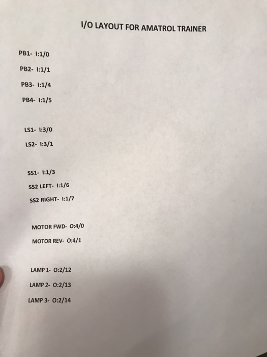
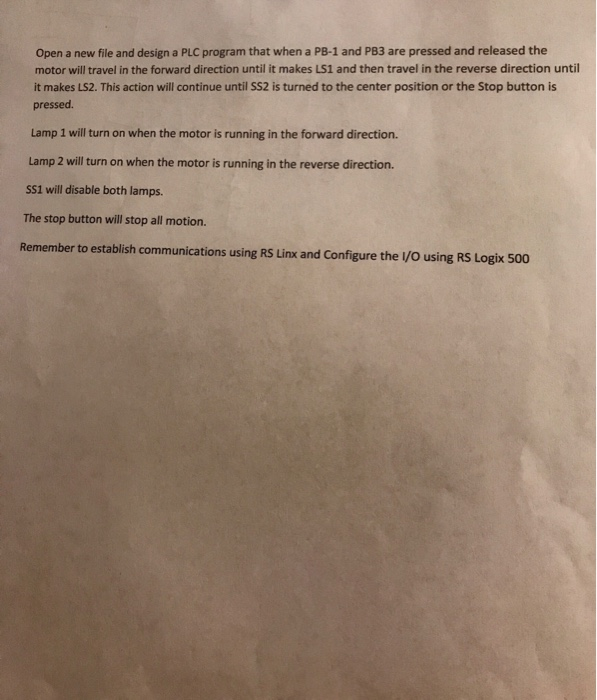
I/O LAYOUT FOR AMATROL TRAINER PB1- 1:1/0 PB2- 1:1/1 PB3- 1:1/4 PB4- 1:1/5 LS1- 1:3/0 LS2- 1:3/1 SS1- 1:1/3 SS2 LEFT- 1:1/6 SS2 RIGHT- 1:1/7 MOTOR FWD- 0:4/0 MOTOR REV- 0:4/1 LAMP 1- 0:2/12 LAMP 2- 0:2/13 LAMP 3- 0:2/14 Open a new file and design a PLC program that when a PB-1 and PB3 are pressed and released the motor will travel in the forward direction until it makes LS1 and then travel in the reverse direction until it makes LS2. This action will continue until SS2 is turned to the center position or the Stop button is pressed Lamp 1 will turn on when the motor is running in the forward direction. Lamp 2 will turn on when the motor is running in the reverse direction. SS1 will disable both lamps. The stop button will stop all motion. Remember to establish communications using RS Linx and Configure the I/O using RS Logix 500
Step by Step Solution
There are 3 Steps involved in it

Get step-by-step solutions from verified subject matter experts