

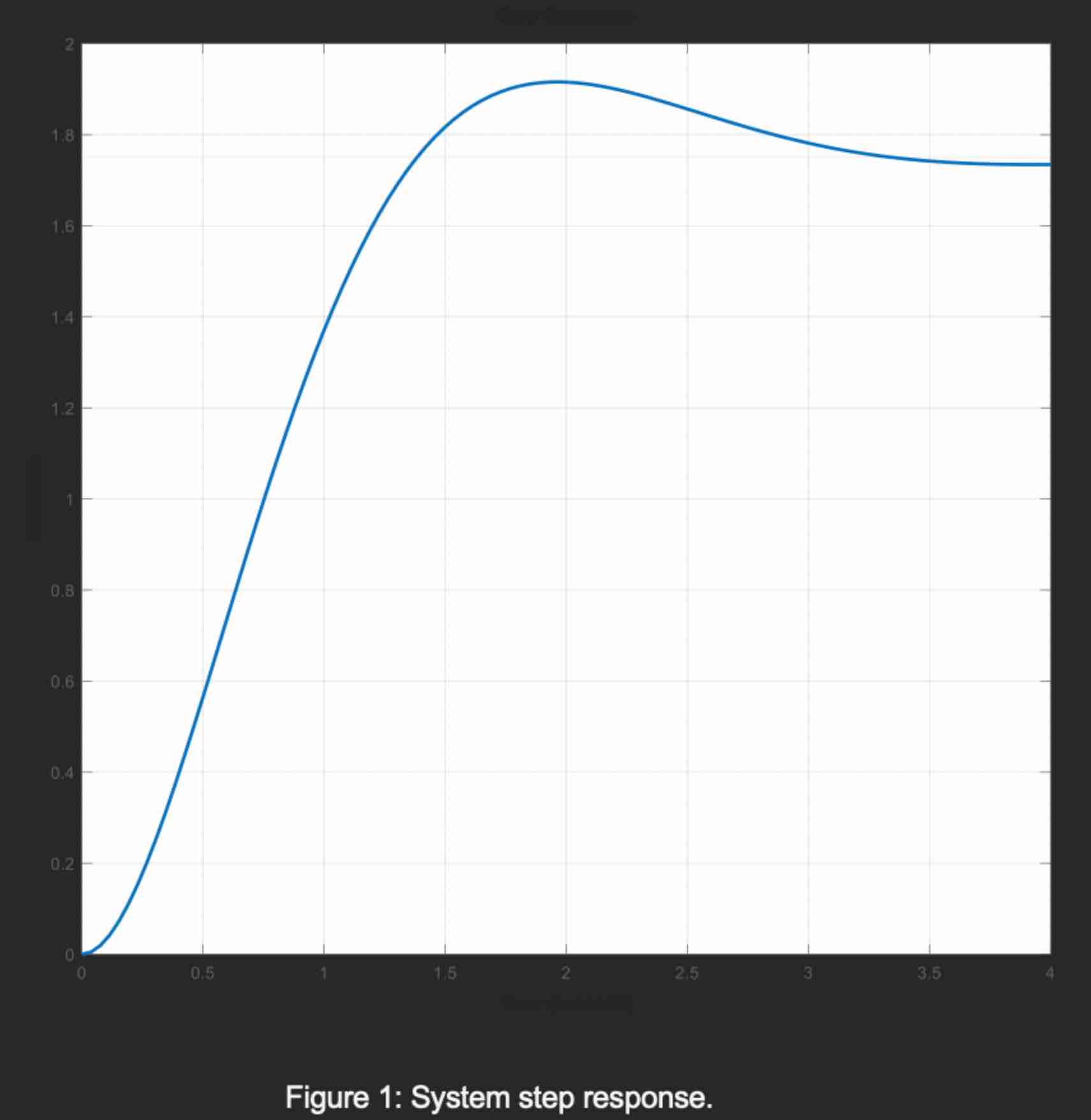
Question: i . Find the transfer function for the system with the unit step response shown in Figure 1 . ii . Plot the location in
i Find the transfer function for the system with the unit step response shown in Figure
ii Plot the location in the plane of the transfer function poles found in part i indicating angles where neccesary.
iii. Determine whether the system described by the forward path transfer function and feedback path is stable.
Figure : System step response.
Step by Step Solution
There are 3 Steps involved in it
1 Expert Approved Answer
Step: 1 Unlock

Question Has Been Solved by an Expert!
Get step-by-step solutions from verified subject matter experts
Step: 2 Unlock
Step: 3 Unlock