

Question: I have all the data about the experiment, fill in the tables and I want answers to the questions urgently. Aims: To examine the relation
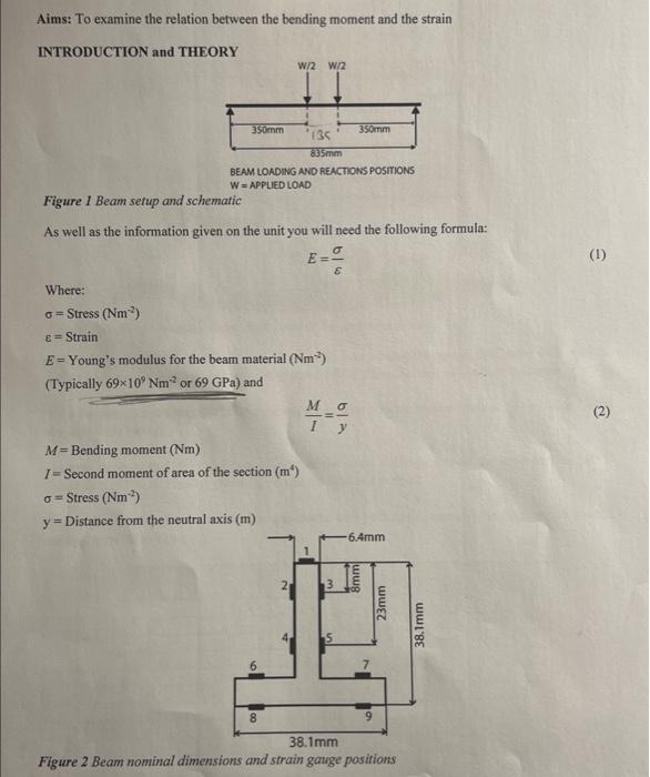
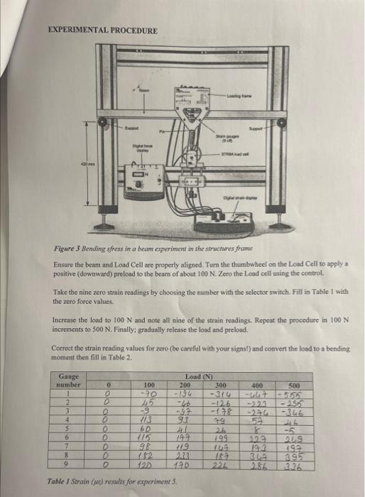
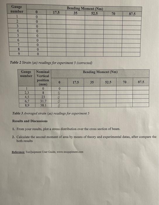
Aims: To examine the relation between the bending moment and the strain INTRODUCTION and THEORY BEAM LOADING AND REACTIONS POSTIONS W = APPLIED LOAD Figure I Beam setup and schematic As well as the information given on the unit you will need the following formula: E= Where: =Stress(Nm2)=Strain E= Young's modulus for the bearn material (Nm2) (Typically 69109Nm2 or 69GPa ) and IM=y M= Bending moment (Nm) I= Second moment of area of the section (m4) =Stress(Nm2) y= Distance from the neutral axis (m) Figure 2 Beam nominal dimensions and strain gange positions EXPERIMENTAL PROCEDURE Figure 3 Bending sfress in a beam experiment in the structures frame Fnsure the beim and Land Cell are properly aligned. Ture the thumbwheel on the Lead Cell to apply a positive (downward) preload to the bearn of about 100N. Zero the Lead cell esing the control. Take the nine zero strain readings by choosing the number with the sclector switch. Fill in Table I with the zero force values. Increase the load to 100N and note all nine of the strain readings. Repeat the procedure in 100N increments to 500N. Finally; gradually release the load and preload. Correct the strain reading values for zero (be carefal with your signs) and convert the lood to a bending moment then fill in Table 2. Table 2 Strain ( ) readings for experiment 5 (corrected) Table 3 Averaged strain ( ) readings for experiment 5 Results and Discussions 1. From your results, plot a stress distribution over the cross section of beam. 2. Calculate the second moment of area by means of theory and experimental datas, after compare the both results Reference: TecQuipment User Guide, www.tecqupiment.com
Step by Step Solution
There are 3 Steps involved in it

Get step-by-step solutions from verified subject matter experts