

Question: I have problem with packet tracker questions. I need you to answer all the questions (written as turn-in) This is what I got from lab1.
I have problem with packet tracker questions.
I need you to answer all the questions (written as turn-in)
This is what I got from lab1.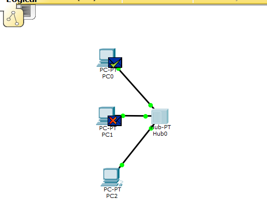
Packet Tracker
Ethernet Broadcasts, Collisions Hubs and Switches
Part 1: Simple PDU and Hubs
Testing connectivity with PDUs
Once a topology has been created, connectivity can be tested between devices by using either simple or complex PDUs. It is possible to do the same by pinging devices from their command-line interface, as we did in lab1.
Load the pkt file from lab1.
Click the "Add Simple PDU" button, as indicated in the figure above. Then click on PC0. Then click on PC2. This launches a Ping packet from PC0 to PC2.
Using the simulation mode
So far we were working in real-time mode, so the only indication of traffic was the link status blinking green. But, using simulation mode, you can see packets flowing from one node to another and can also click on a packet to see detailed information categorized by OSI layers.
Use the realtime/simulation tab to switch to the simulation mode.
Click on the Auto Capture / Play button to begin packet capture. Try a Simple PDU, as described in the previous section, and the event list will be populated with entries, indicating the creation of an ICMP packet, ICMP echo sent, and ICMP reply received
The simulation mode has a Play Controls section that functions as follows:
Back: This button moves the process one step back each time it is clicked on.
Auto Capture / Play: Pressing this button results in all of the network traffic (chosen under event filters) being continuously captured until this button is pressed again.
Capture/Forward: This is the manual mode of the previous button. This has to be pressed each time to move the packet from one place to another
If you click on a packet (the envelope icon), you'll be presented with the packet information categorized according to OSI layers. The InBound/Outbound PDU Details tab lists each layer's information in a packet format:
Notice that the single Ping sent from PC0 is delivered to both PC1 and PC2 by the hub.
Turn in: Explain why the single Ping is sent to both PC1 and PC2, while the IP and Ethernet header specifies PC2? ______
You should see an ICMP response from PC2 going to both PC0 and PC1.
When the simulation is complete, you should see the screen below, showing green envelopes on PC0 and PC1. There is a green check mark on PC0 and a red X on PC1.
Turn in: Explain what does the red X on PC1 mean? ______
Collision
Add three more PCs - PC3, PC4, and PC5 into the topology.
Use simple PDU to ping PC5 from PC0. At the same time ping PC0 from PC3. Simulate and observe collisions.
Part 2: Switched Network
Keep the Hub topology and set up a similar star topology, but with a Switch. In Edit Filters, select filter ARP and ICMP only (may not be visible on the lab computers due to scaling issues).
Configure the PCs with the following IP addresses in the table.
Step 1: Turn in: Fill in the MAC addresses in the table.
Addressing Table
| Device | Interface | MAC Address | Switch Interface |
| PC6 - 192.168.2.100 | Fa0 |
| Fa0/1 |
| PC7 - 192.168.2.101 | Fa0 |
| Fa0/2 |
| PC8 - 192.168.2.102 | Fa0 |
| Fa0/3 |
| PC9 - 192.168.2.103 | Fa0 |
| Fa0/4 |
| PC10 - 192.168.2.104 | Fa0 |
| Fa0/5 |
| PC11 - 192.168.2.105 | Fa0 |
| Fa0/6 |
Examine an ARP Request
Turn in Answers to the following questions:
Step 2: Generate ARP requests by pinging PC9 from PC6.
Click PC6 and open the Command Prompt.
Enter the arp -d command to clear the ARP table.
Enter Simulation mode and enter the command ping 192.168.2.103. Two PDUs will be generated. The ping command cannot complete the ICMP packet without knowing the MAC address of the destination. So the computer sends an ARP broadcast frame to find the MAC address of the destination.
Click Capture/Forward once. The ARP PDU moves to Switch0 while the ICMP PDU disappears, waiting for the ARP reply. Open the PDU and record the destination MAC address. What is the address, and is this address listed in the table above? ______
Click Capture/Forward to move the PDU to the next device. How many copies of the PDU did Switch0 make? _____
What is the IP address of the device that accepted the PDU? ______
Click Capture/Forward once to move the PDU. Open the PDU and examine Layer 2. What happened to the source and destination MAC addresses in comparison with step (d) above? ______
Click Capture/Forward until the PDU returns to PC9. How many copies of the PDU did the switch make during the ARP reply? ______
Step 3:Examine the ARP table.
Note that the ICMP packet reappears. Open the PDU and examine the MAC addresses. Do the MAC addresses of the source and destination align with their IP addresses? ______
Click Capture/Forward to complete the ping.
Click PC6 and enter the arp a command. To what IP address does the MAC address entry correspond? ______
In general, when does an end device issue an ARP request? ______
Examine a Switch MAC Address Table
Step 4:Examine the MAC address table on the switches.
Click Switch0 and then the CLI tab. Enter the show mac-address-table command. Do the entries correspond to those in the addressing table in step1? ______
Generate additional traffic to populate the switch MAC address table. List your switch MAC table below. ______
Examine Collisions
Step 5:Examine collisions in switched network
Use simple PDU to ping PC7 from PC6. At the same time ping PC6 from PC9. Simulate. Is there collision? Explain why or why not. Turn in Answers. ______
PC -F PCO ub-PT Hub0 PC -P PC1 PC-PT PC2 PC -F PCO ub-PT Hub0 PC -P PC1 PC-PT PC2
Step by Step Solution
There are 3 Steps involved in it

Get step-by-step solutions from verified subject matter experts