

Question: DAN ANALYSIS WEEN MANALYSIS 5-15 Problem 5-15 ANALYSIS. 5-16 Problem 5-16 5-17 Problem 5-17 A rectangular steel bar supports the two overhanging loads shown
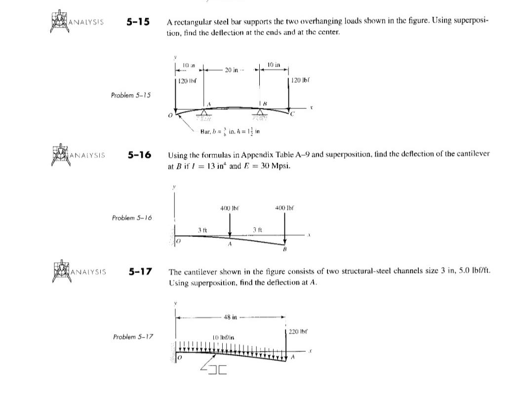
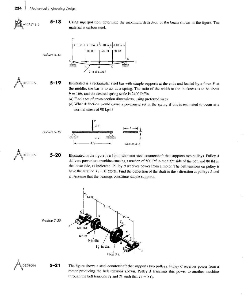

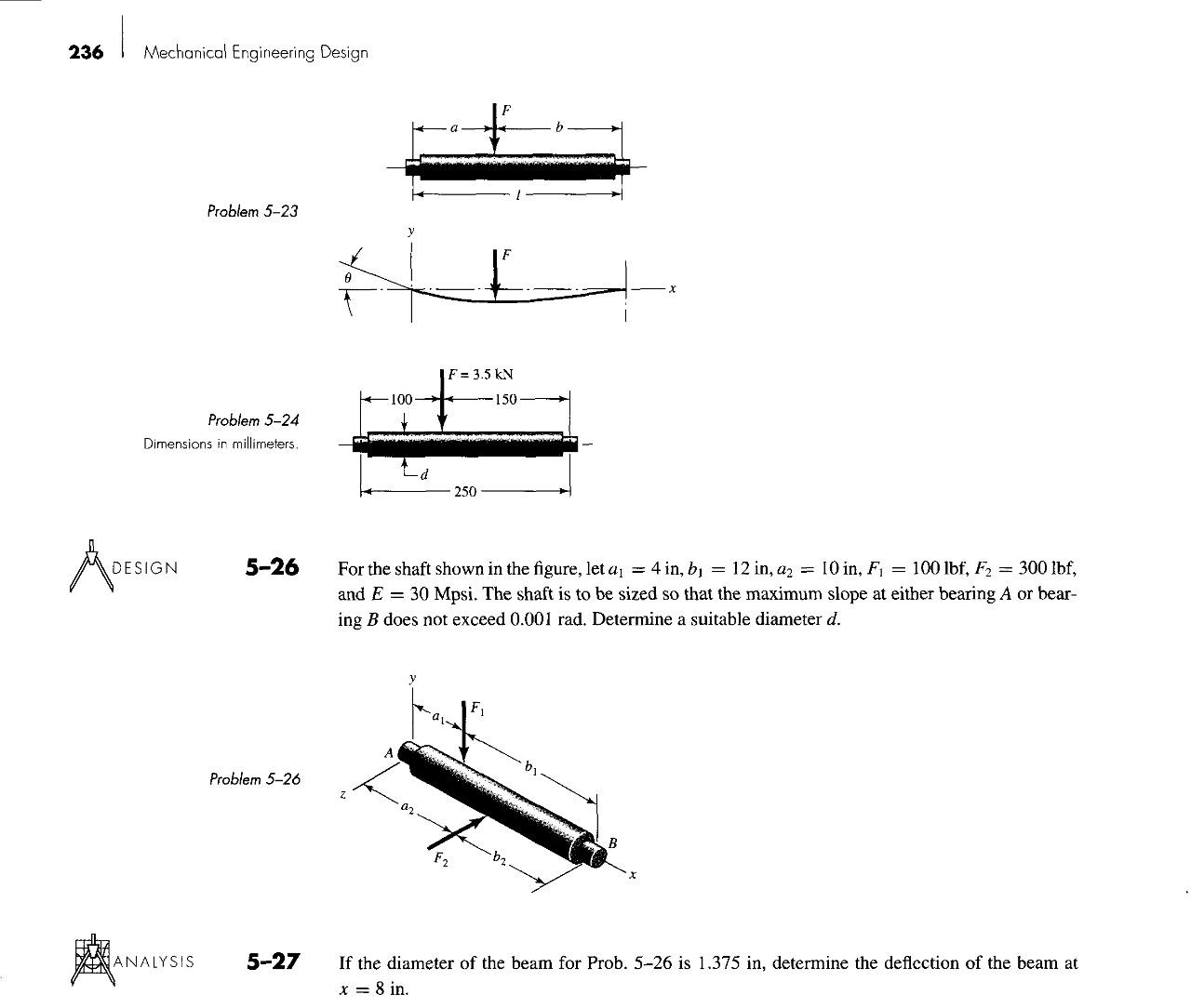
DAN ANALYSIS WEEN MANALYSIS 5-15 Problem 5-15 ANALYSIS. 5-16 Problem 5-16 5-17 Problem 5-17 A rectangular steel bar supports the two overhanging loads shown in the figure. Using superposi- tion, find the deflection at the ends and at the center. 0 V 10 n 120 lbf 20 in AN Bar, b = in. = 1 in A 18 48 in 10 in JUBRE 10 lbf/in Using the formulas in Appendix Table A-9 and superposition, find the deflection of the cantilever at B if I = 13 in and E = 30 Mpsi. 400 lbf 400 lbf IJ 3 ft GE 1 120 lbf C B The cantilever shown in the figure consists of two structural-steel channels size 3 in, 5.0 lbf/ft. Using superposition, find the deflection at A. r A 220 lbf A 8 234 1 Mechanical Engineering Design ANALYSIS DE DESIGN DESIGN ADESI DESIGN 5-18 Problem 5-18 5-19 Problem 5-19 5-20 Problem 5-20 5-21 Using superposition, determine the maximum deflection of the beam shown in the figure. The material is carbon steel. y 10 in-10 in 10 in 10 in 80 lbf 120 lbf 80 lbf 0 SURE A 22-in-di INSHE 600 lbf B - 2-in-dia. shaft 80 lbf Illustrated is a rectangular steel bar with simple supports at the ends and loaded by a force F at the middle; the bar is to act as a spring. The ratio of the width to the thickness is to be about b = 16h, and the desired spring scale is 2400 lbf/in. (a) Find a set of cross-section dimensions, using preferred sizes. (b) What deflection would cause a permanent set in the spring if this is estimated to occur at a normal stress of 90 kpsi? fin 4 ft A C DEASURE 21 in Illustrated in the figure is a 12-in-diameter steel countershaft that supports two pulleys. Pulley A delivers power to a machine causing a tension of 600 lbf in the tight side of the belt and 80 lbf in the loose side, as indicated. Pulley B receives power from a motor. The belt tensions on pulley B have the relation T = 0.1257. Find the deflection of the shaft in the z direction at pulleys A and B. Assume that the bearings constitute simple supports. FIZIR 9-in dia. 1-in dia. D A SAN B 12-in dia. T Section A-A 15 in b T The figure shows a steel countershaft that supports two pulleys. Pulley C receives power from a motor producing the belt tensions shown. Pulley A transmits this power to another machine through the belt tensions T, and T such that T = 87. DESIGN ANALYSIS DE DESIGN ANALYSIS Problem 5-21 5-22 5-23 5-24 5-25 10-in dia. T 9 in 16-in dia. 11 in 1-in dia. B d = 400 lbf 12 in (a) Find the deflection of the overhanging end of the shaft, assuming simple supports at the bearings. (b) If roller bearings are used, the slope of the shaft at the bearings should not exceed 0.06 for good bearing life. What shaft diameter is needed to conform to this requirement? Use -in increments in any iteration you may make. What is the deflection at pulley C now? 50 lbf The structure of a diesel-electric locomotive is essentially a composite beam supporting a deck. Above the deck are mounted the diesel prime mover, generator or alternator, radiators, switch gear, and auxiliaries. Beneath the deck are found fuel and lubricant tanks, air reservoirs, and small auxiliaries. This assembly is supported at bolsters by the trucks that house the traction motors and brakes. This equipment is distributed as uniformly as possible in the span between the bolsters. In an approximate way, the loading can be viewed as uniform between the bolsters and simply sup- ported. Because the hoods that shield the equipment from the weather have many rectangular access doors, which are mass-produced, it is important that the hood structure be level and plumb and sit on a flat deck. Aesthetics plays a role too. The center sill beam has a second moment of area of 1 = 5450 in*, the bolsters are 36 ft apart, and the deck loading is 5000 lbf/ft. (a) What is the camber of the curve to which the deck will be built in order that the service-ready locomotive will have a flat deck? (b) What equation would you give to locate points on the curve of part (a)? 32Fb(1-b) 3 ELE The designer of a shaft usually has a slope constraint imposed by the bearings used. This limit will be denoted as . If the shaft shown in the figure is to have a uniform diameter d except in the locality of the bearing mounting, it can be approximated as a uniform beam with simple supports. Show that the minimum diameters to meet the slope constraints at the left and right bearings are, respectively. 11/4 Deflection and Stiffness 235 dk = 32Fa(1-a) El 11/4 A shaft is to be designed so that it is supported by roller bearings. The basic geometry is shown in the figure. The allowable slope at the bearings is 0.001 mm/mm without bearing life penalty. For a design factor of 1.28, what uniform-diameter shaft will support the 3.5-kN load 100 mm from the left bearing without penalty? Use E = 207 GPa. Determine the maximum deflection of the shaft of Prob. 5-24. 236 Mechanical Engineering Design Problem 5-24 Dimensions in millimeters. DESIGN Problem 5-23 ANALYSIS 5-26 Problem 5-26 5-27 0 100- IF = 3.5 kN -150 y For the shaft shown in the figure, let a = 4 in, b = 12 in, a = 10 in, F = 100 lbf, F = 300 lbf, and E 30 Mpsi. The shaft is to be sized so that the maximum slope at either bearing A or bear- ing B does not exceed 0.001 rad. Determine a suitable diameter d. 250 -01- F2 by If the diameter of the beam for Prob. 5-26 is 1.375 in, determine the deflection of the beam at x = 8 in. DAN ANALYSIS WEEN MANALYSIS 5-15 Problem 5-15 ANALYSIS. 5-16 Problem 5-16 5-17 Problem 5-17 A rectangular steel bar supports the two overhanging loads shown in the figure. Using superposi- tion, find the deflection at the ends and at the center. 0 V 10 n 120 lbf 20 in AN Bar, b = in. = 1 in A 18 48 in 10 in JUBRE 10 lbf/in Using the formulas in Appendix Table A-9 and superposition, find the deflection of the cantilever at B if I = 13 in and E = 30 Mpsi. 400 lbf 400 lbf IJ 3 ft GE 1 120 lbf C B The cantilever shown in the figure consists of two structural-steel channels size 3 in, 5.0 lbf/ft. Using superposition, find the deflection at A. r A 220 lbf A 8 234 1 Mechanical Engineering Design ANALYSIS DE DESIGN DESIGN ADESI DESIGN 5-18 Problem 5-18 5-19 Problem 5-19 5-20 Problem 5-20 5-21 Using superposition, determine the maximum deflection of the beam shown in the figure. The material is carbon steel. y 10 in-10 in 10 in 10 in 80 lbf 120 lbf 80 lbf 0 SURE A 22-in-di INSHE 600 lbf B - 2-in-dia. shaft 80 lbf Illustrated is a rectangular steel bar with simple supports at the ends and loaded by a force F at the middle; the bar is to act as a spring. The ratio of the width to the thickness is to be about b = 16h, and the desired spring scale is 2400 lbf/in. (a) Find a set of cross-section dimensions, using preferred sizes. (b) What deflection would cause a permanent set in the spring if this is estimated to occur at a normal stress of 90 kpsi? fin 4 ft A C DEASURE 21 in Illustrated in the figure is a 12-in-diameter steel countershaft that supports two pulleys. Pulley A delivers power to a machine causing a tension of 600 lbf in the tight side of the belt and 80 lbf in the loose side, as indicated. Pulley B receives power from a motor. The belt tensions on pulley B have the relation T = 0.1257. Find the deflection of the shaft in the z direction at pulleys A and B. Assume that the bearings constitute simple supports. FIZIR 9-in dia. 1-in dia. D A SAN B 12-in dia. T Section A-A 15 in b T The figure shows a steel countershaft that supports two pulleys. Pulley C receives power from a motor producing the belt tensions shown. Pulley A transmits this power to another machine through the belt tensions T, and T such that T = 87. DESIGN ANALYSIS DE DESIGN ANALYSIS Problem 5-21 5-22 5-23 5-24 5-25 10-in dia. T 9 in 16-in dia. 11 in 1-in dia. B d = 400 lbf 12 in (a) Find the deflection of the overhanging end of the shaft, assuming simple supports at the bearings. (b) If roller bearings are used, the slope of the shaft at the bearings should not exceed 0.06 for good bearing life. What shaft diameter is needed to conform to this requirement? Use -in increments in any iteration you may make. What is the deflection at pulley C now? 50 lbf The structure of a diesel-electric locomotive is essentially a composite beam supporting a deck. Above the deck are mounted the diesel prime mover, generator or alternator, radiators, switch gear, and auxiliaries. Beneath the deck are found fuel and lubricant tanks, air reservoirs, and small auxiliaries. This assembly is supported at bolsters by the trucks that house the traction motors and brakes. This equipment is distributed as uniformly as possible in the span between the bolsters. In an approximate way, the loading can be viewed as uniform between the bolsters and simply sup- ported. Because the hoods that shield the equipment from the weather have many rectangular access doors, which are mass-produced, it is important that the hood structure be level and plumb and sit on a flat deck. Aesthetics plays a role too. The center sill beam has a second moment of area of 1 = 5450 in*, the bolsters are 36 ft apart, and the deck loading is 5000 lbf/ft. (a) What is the camber of the curve to which the deck will be built in order that the service-ready locomotive will have a flat deck? (b) What equation would you give to locate points on the curve of part (a)? 32Fb(1-b) 3 ELE The designer of a shaft usually has a slope constraint imposed by the bearings used. This limit will be denoted as . If the shaft shown in the figure is to have a uniform diameter d except in the locality of the bearing mounting, it can be approximated as a uniform beam with simple supports. Show that the minimum diameters to meet the slope constraints at the left and right bearings are, respectively. 11/4 Deflection and Stiffness 235 dk = 32Fa(1-a) El 11/4 A shaft is to be designed so that it is supported by roller bearings. The basic geometry is shown in the figure. The allowable slope at the bearings is 0.001 mm/mm without bearing life penalty. For a design factor of 1.28, what uniform-diameter shaft will support the 3.5-kN load 100 mm from the left bearing without penalty? Use E = 207 GPa. Determine the maximum deflection of the shaft of Prob. 5-24. 236 Mechanical Engineering Design Problem 5-24 Dimensions in millimeters. DESIGN Problem 5-23 ANALYSIS 5-26 Problem 5-26 5-27 0 100- IF = 3.5 kN -150 y For the shaft shown in the figure, let a = 4 in, b = 12 in, a = 10 in, F = 100 lbf, F = 300 lbf, and E 30 Mpsi. The shaft is to be sized so that the maximum slope at either bearing A or bear- ing B does not exceed 0.001 rad. Determine a suitable diameter d. 250 -01- F2 by If the diameter of the beam for Prob. 5-26 is 1.375 in, determine the deflection of the beam at x = 8 in.
Step by Step Solution
3.45 Rating (161 Votes )
There are 3 Steps involved in it
1 2 3 Sor... View full answer

Get step-by-step solutions from verified subject matter experts