

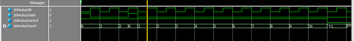
Question: I need help implementing an 8 - bit Up / Down counter system in Verilog. Please provide three files: counter.v - The main counter module
I need help implementing an bit UpDown counter system in Verilog. Please provide three files:
counter.v The main counter module with these specifications: Inputs:
clk clock signal
reset active high reset
control updown control signal Output:
count:bit counter value
Requirements:
When reset is counter resets to
When control is count up
When control is count down
Use two always blocks:
First block: posedge clk to latch control signal to ctrl Second block: negedge clk or posedge reset for counting based on ctrl
main.v Toplevel module that:
Instantiates the counter module
Connects all necessary ports
stimulus.v Testbench that:
Generates clock signal
Tests reset functionality
Tests both up and down counting
Verifies counter behavior with different control values
Includes proper simulation time and waveform monitoring
Please provide the complete Verilog code for all three files to create a fully functional and testable UpDown counter system.
Step by Step Solution
There are 3 Steps involved in it
1 Expert Approved Answer
Step: 1 Unlock

Question Has Been Solved by an Expert!
Get step-by-step solutions from verified subject matter experts
Step: 2 Unlock
Step: 3 Unlock