

Question: I need help in MATLAB simulink tool. How do I use Simulink to create a control system to express a 2nd order differential equation? This
I need help in MATLAB simulink tool. How do I use Simulink to create a control system to express a 2nd order differential equation?
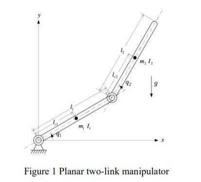
This is the diagram:
I'm given this equation:
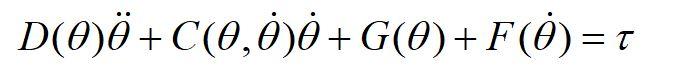
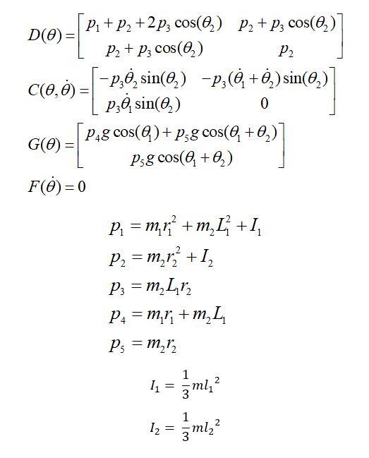
, where matrix D, C, G and F can be represented by
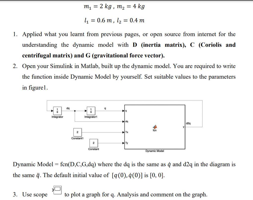
I'm supposed to design a control system that looks like this:
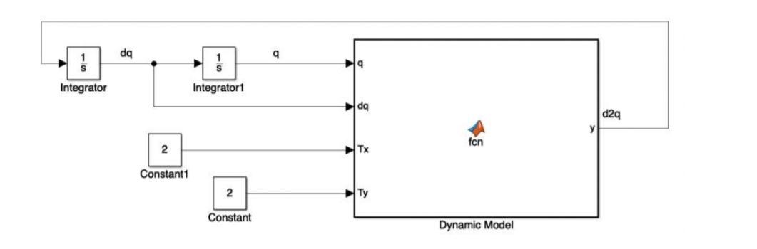
I am given that the dynamic model = fcn(D,C,G,dq) where the dq is the same as and d2q in the diagram is the same . The default initial value of [(0), (0)] is [0, 0].
My code is here:
function torque = fcn(D,C,G,theta,omega)
% length of the 2 robotic arms
l1 = 1;
l2=1;
r1=l1/2;
r2=l2/2;
% mass of the 2 robotic arms
m1= 5;
m2=5;
% moment of inertia of the 2 robotic arms
I1= (m1*l1^2)/3;
I2 = (m2*l2^2)/3;
p1= m1*r1^2+m2*l1^2+I1;
p2= m2*r2^2+ I2;
p3= m2*l1*r2;
p4= m1*r1+m2*l1;
p5= m2*r2;
% gravitational field strength
g = 9.81
D(theta) = [p1+p2+2*p3*cos(theta(2)) p2+p3*cos(theta(2)); p2+p3*cos(theta(2)) p2];
C(theta, omega) = [-p3*omega(2)*sin(theta(2)) -p3*(omega(1)+omega(2))*sin(theta(2)); p3*omega(1)*sin(theta(2)) 0];
G(theta) = [p4*g*theta((1))+ p5*g*cos(theta(1)+theta(2)); p5*g*cos(theta(1)+theta(2))];
F(omega) = 0
dthetadt = omega;
domegadt = D(theta)\(tau-F(omega)-G(theta)-C(theta,omega)*omega);
% Define Conditions
theta(1) = linspace(0, pi/2,10);
theta(2) = linspace(0,pi/2,10);
Is my code correct? And how to create a control system to represent the 2nd ode equation. Can someone help me? I'm pretty new to SimuLink and Matlab
* m, 1, 9 Figure 1 Planar two-link manipulator D(0)+C(0,0))+G(0)+F(0) = + =T P. + P2 +2pz cos(0) P2 + pz cos(@)] D(O)= P2 + P, cos(@) P2 T-) )] p.), sin(0) Pag cos(@)+Pg cos(@+0)] G(O) = Psg cos(@+) FO)=0 C(0,0) = =p,, sin(0) -P;(0 +0.) sin(0,) -=[ P8 0 = = = = P1 = m,+m, L +1, P2 = m_r2 +1, P2 = m Lr2 P4 = m,ri+m L Ps = m 2 = = = 1 mli 2 113 1 2 12 = 3 ml, da 9 19 Integrator Integratori da d2q fon 2 HTx Constant1 2 HTy Constant Dynamic Model m = 2 kg, m2 = 4 kg = 11 = 0.6 m, l2 = 0.4 m = = 1. Applied what you learnt from previous pages, or open source from internet for the understanding the dynamic model with D (inertia matrix), C (Coriolis and centrifugal matrix) and G (gravitational force vector). 2. Open your Simulink in Matlab, built up the dynamic model. You are required to write the function inside Dynamic Model by yourself. Set suitable values to the parameters in figurel. da 9 Integrator Integratori da d29 ten 2 HTX Constant 2 Constant Dynamic Model = Dynamic Model = fcn(D,C,G,dq) where the dq is the same as q and d2q in the diagram is the same q. The default initial value of [9(0),(0)] is [0, 0]. 3. Use scope to plot a graph for q. Analysis and comment on the graph. . * m, 1, 9 Figure 1 Planar two-link manipulator D(0)+C(0,0))+G(0)+F(0) = + =T P. + P2 +2pz cos(0) P2 + pz cos(@)] D(O)= P2 + P, cos(@) P2 T-) )] p.), sin(0) Pag cos(@)+Pg cos(@+0)] G(O) = Psg cos(@+) FO)=0 C(0,0) = =p,, sin(0) -P;(0 +0.) sin(0,) -=[ P8 0 = = = = P1 = m,+m, L +1, P2 = m_r2 +1, P2 = m Lr2 P4 = m,ri+m L Ps = m 2 = = = 1 mli 2 113 1 2 12 = 3 ml, da 9 19 Integrator Integratori da d2q fon 2 HTx Constant1 2 HTy Constant Dynamic Model m = 2 kg, m2 = 4 kg = 11 = 0.6 m, l2 = 0.4 m = = 1. Applied what you learnt from previous pages, or open source from internet for the understanding the dynamic model with D (inertia matrix), C (Coriolis and centrifugal matrix) and G (gravitational force vector). 2. Open your Simulink in Matlab, built up the dynamic model. You are required to write the function inside Dynamic Model by yourself. Set suitable values to the parameters in figurel. da 9 Integrator Integratori da d29 ten 2 HTX Constant 2 Constant Dynamic Model = Dynamic Model = fcn(D,C,G,dq) where the dq is the same as q and d2q in the diagram is the same q. The default initial value of [9(0),(0)] is [0, 0]. 3. Use scope to plot a graph for q. Analysis and comment on the graph
Step by Step Solution
There are 3 Steps involved in it

Get step-by-step solutions from verified subject matter experts