

Question: I need help with this lab, I do not understand how to set things up. Please, PLEASE, do not just rewrite what is already there.
I need help with this lab, I do not understand how to set things up. Please, PLEASE, do not just rewrite what is already there. That does not help me.
Pictures help me understand what I need to do with this.
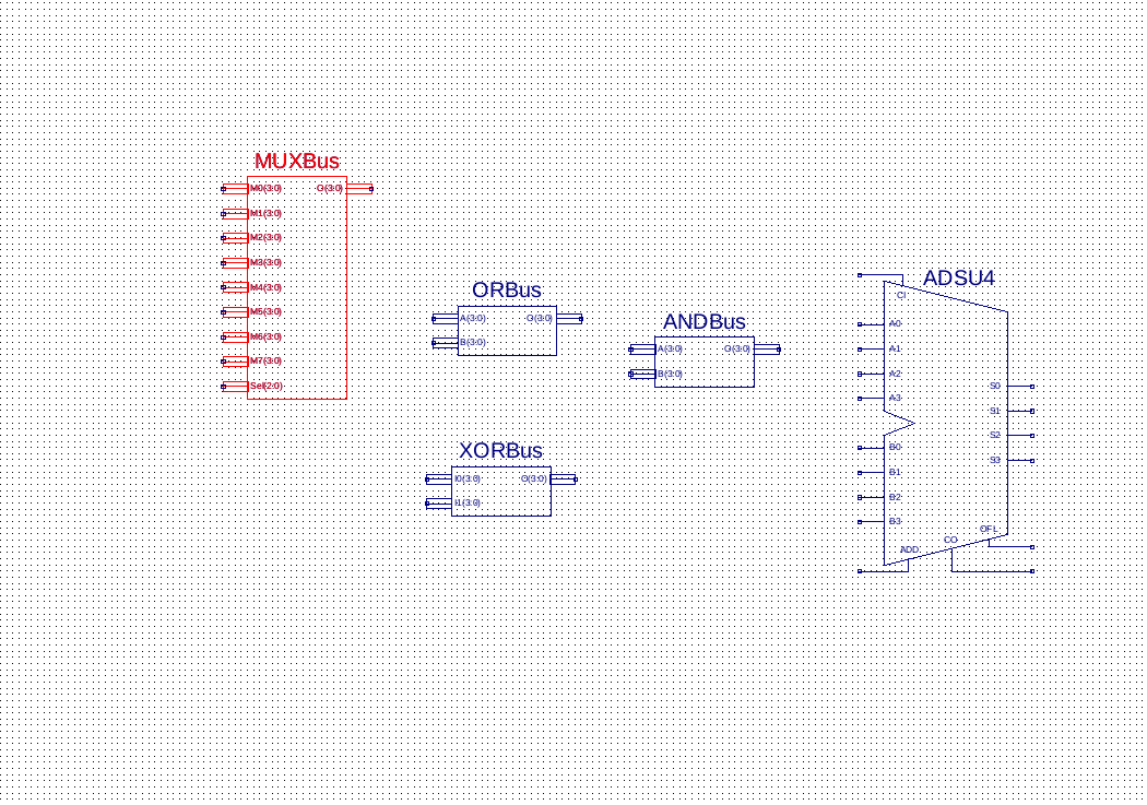
These are the symbols I have already, but, I need help on how to connect these as well as the ones that I do not have.
PLEASE do not just write out how to do it. That does not help. I already have it in words above. I need pictures to understand how to connect everything.
 I need help ASAP, please.
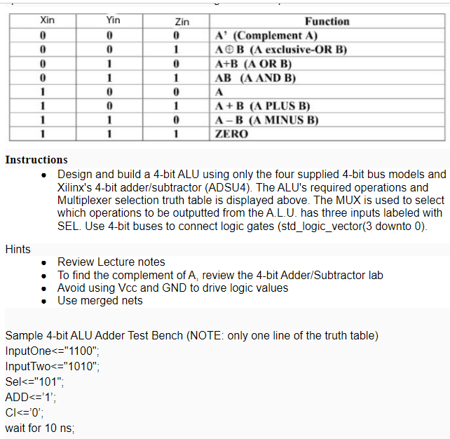
Instructions - Design and build a 4-bit ALU using only the four supplied 4-bit bus models and Xilinx's 4-bit adder/subtractor (ADSU4). The ALU's required operations and Multiplexer selection truth table is displayed above. The MUX is used to select which operations to be outputted from the A.L.U. has three inputs labeled with SEL. Use 4-bit buses to connect logic gates (std_logic_vector(3 downto 0). Hints - Review Lecture notes - To find the complement of A, review the 4-bit Adder/Subtractor lab - Avoid using Vcc and GND to drive logic values - Use merged nets Sample 4-bit ALU Adder Test Bench (NOTE: only one line of the truth table) InputOne
Step by Step Solution
There are 3 Steps involved in it

Get step-by-step solutions from verified subject matter experts