

Question: Procedure Part B (Motor Starter) 1- Connect the main motor circuit as shown in fig.2. 2- Connect the control circuit shown in fig.3 in
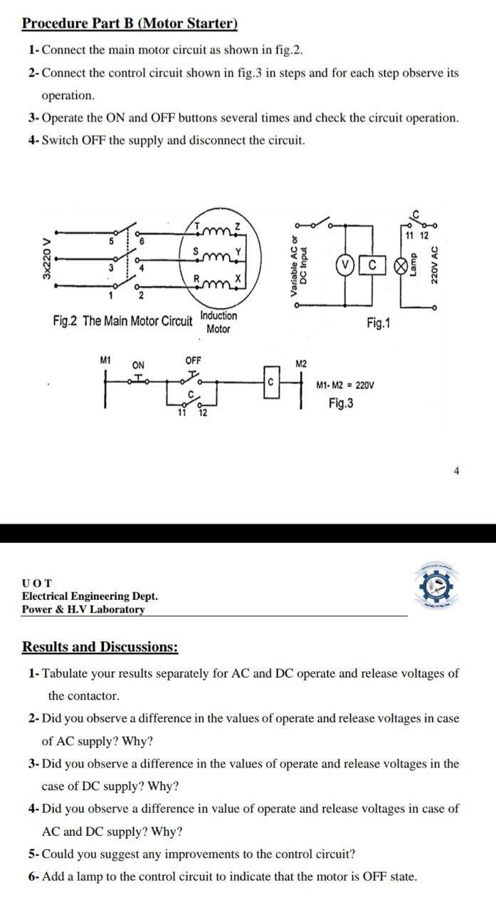
Procedure Part B (Motor Starter) 1- Connect the main motor circuit as shown in fig.2. 2- Connect the control circuit shown in fig.3 in steps and for each step observe its operation. 3- Operate the ON and OFF buttons several times and check the circuit operation. 4- Switch OFF the supply and disconnect the circuit. Fig.2 The Main Motor Circuit M1 ON Tim smr Rmx UOT Electrical Engineering Dept. Power & H.V Laboratory Induction Motor OFF 11 12 M2 C Fig.1 M1-M2 = 220V Fig.3 Results and Discussions: 1- Tabulate your results separately for AC and DC operate and release voltages of the contactor. 2- Did you observe a difference in the values of operate and release voltages in case of AC supply? Why? 3- Did you observe a difference in the values of operate and release voltages in the case of DC supply? Why? 4- Did you observe a difference in value of operate and release voltages in case of AC and DC supply? Why? 5- Could you suggest any improvements to the control circuit? 6- Add a lamp to the control circuit to indicate that the motor is OFF state.
Step by Step Solution
3.45 Rating (155 Votes )
There are 3 Steps involved in it
Results and Discussions 1 Tabulate your results separately for AC and DC operate and release voltages of the contactor Table 1 Operate and Release Vol... View full answer

Get step-by-step solutions from verified subject matter experts