

Question: I NEED YOUR HELP TO WRITE THE COMMAND TO SOLVE EACH TASK IN FUL DETAIL ISP and SOHO Addressing Table Name of Subnet CIDR VLAN
I NEED YOUR HELP TO WRITE THE COMMAND TO SOLVE EACH TASK IN FUL DETAIL
| ISP and SOHO Addressing Table | ||||
| Name of Subnet | CIDR VLAN v4 Network Description | |||
| FW to ISP | /28 |
| 209.165.xx.0/28 | Link from ISP to FW |
| ISP to SOHO GW | /29 |
| 198.51.xx.0/29 | Link from ISP to SOHO Router |
| Public Web Servers | /30 |
| 192.0.xx.200/30 | Server |
| Root DNS Server | /30 |
| 1.0.xx.1 | Server |
| SOHO Laptop | /24 |
| 192.168.1.0 /24 | SOHO Laptop |
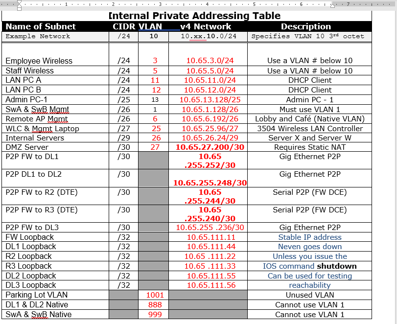
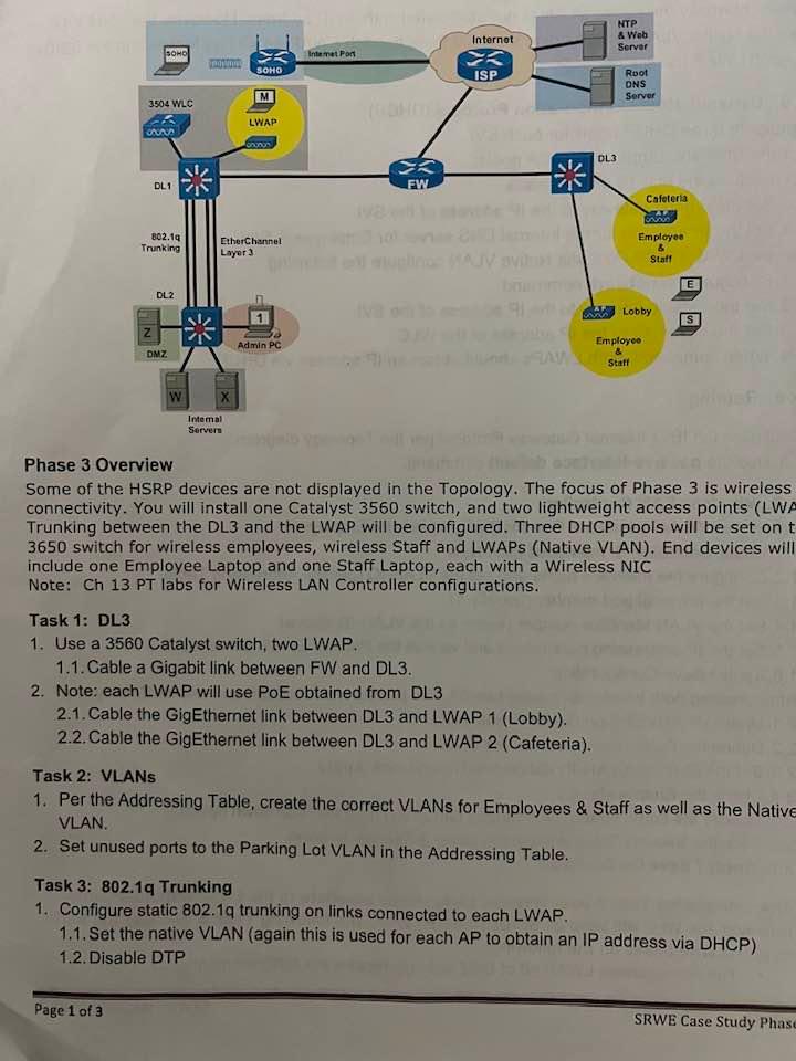
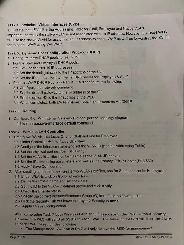
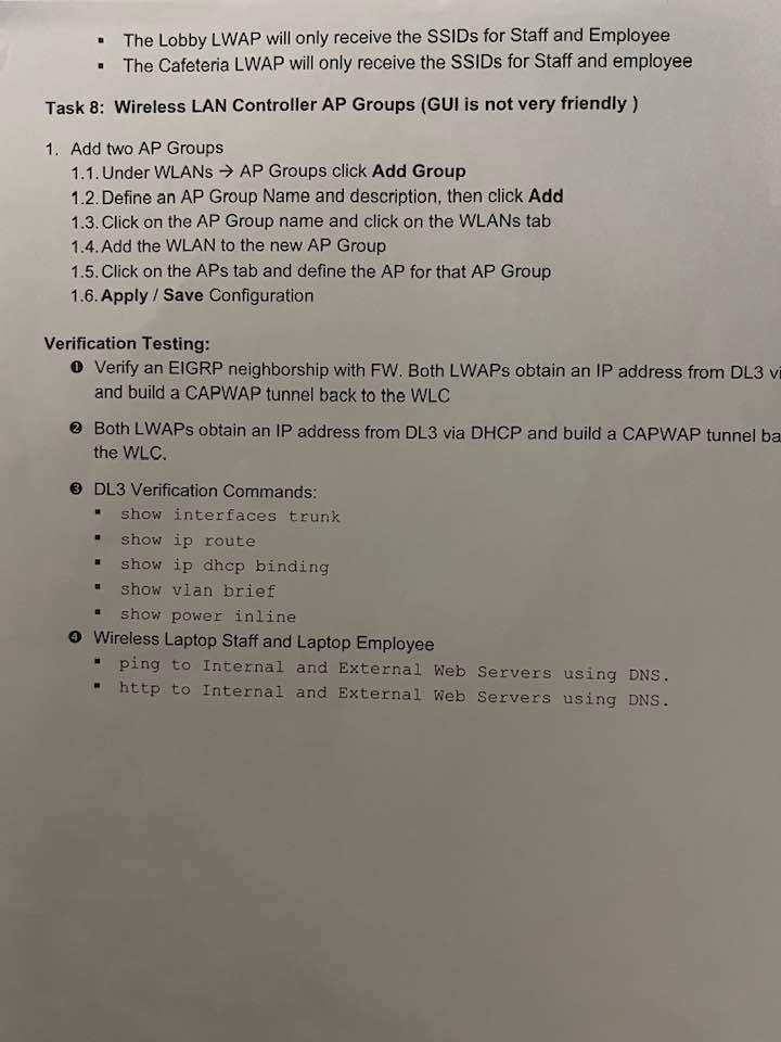
[nternal Private Addressing Table \begin{tabular}{|l|c|c|c|c|} \hline NameofSubnetExampleNetwork & /24 & 10 & 10.xx.10.0/24 & Specifies VLAN 10 3rd octet \\ \hline \hline & & & & \\ Employee Wireless & /24 & 3 & 10.65.3.0/24 & Use a VLAN \# below 10 \\ \hline Staff Wireless & /24 & 5 & 10.65.5.0/24 & Use a VLAN \# below 10 \\ \hline LAN PC A & /24 & 11 & 10.65.11.0/24 & DHCP Client \\ \hline LAN PC B & /24 & 12 & 10.65.12.0/24 & DHCP Client \\ \hline Admin PC-1 & /25 & 13 & 10.65.13.128/25 & Admin PC - 1 \\ \hline SwA \& SwB Mamt & /26 & 1 & 10.65.1.128/26 & Must use VLAN 1 \\ \hline Remote AP Mgmt & /26 & 6 & 10.65.6.192/26 & Lobby and Caf (Native VLAN) \\ \hline WLC \& Mamt Laptop & /27 & 25 & 10.65.25.96/27 & 3504 Wireless LAN Controller \\ \hline Internal Servers & /29 & 26 & 10.65.26.24/29 & Server X and Server W \\ \hline DMZ Server & /30 & 27 & 10.65.27.200/30 & Requires Static NAT \\ \hline P2P FW to DL1 & /30 & & 10.65 & Gig Ethernet P2P \\ \hline P2P DL1 to DL2 & /30 & & 10.65.255.252/30 & Gig Ethernet P2P \\ \hline P2P FW to R2 (DTE) & /30 & & 10.65 & Serial P2P (FW DCE) \\ \hline P2P FW to R3 (DTE) & /30 & &. 10.65 & \\ \hline P2P FW to DL3 & /30 & & 10.65.255.236/30 & Serial P2P (FW DCE) \\ \hline FW Loopback & /32 & & 10.65.111.11 & Gig Ethernet P2P \\ \hline DL1 Loopback & /32 & & 10.65.111.44 & Stable IP address \\ \hline R2 Loopback & /32 & & 10.65.111.22 & Unless you issue the \\ \hline R3 Loopback & /32 & & 10.65.111.33 & IOS command shutdown \\ \hline DL2 Loopback & /32 & & 10.65.111.55 & Can be used for testing \\ \hline DL3 Loopback & /32 & & 10.65.111.56 & reachability \\ \hline Parking Lot VLAN & & 1001 & & Unused VLAN \\ \hline DL1 \& DL2 Native & & 888 & & Cannot use VLAN 1 \\ \hline SwA \& SwB Native & & 999 & & Cannot use VLAN 1 \\ \hline \end{tabular} Phase 3 Overview Some of the HSRP devices are not displayed in the Topology. The focus of Phase 3 is wireless connectivity. You will install one Catalyst 3560 switch, and two lightweight access points (LWA Trunking between the DL3 and the LWAP will be configured. Three DHCP pools will be set on t 3650 switch for wireless employees, wireless Staff and LWAPs (Native VLAN). End devices will include one Employee Laptop and one Staff Laptop, each with a Wireless NIC Note: Ch 13 PT labs for Wireless LAN Controller configurations. Task 1: DL3 1. Use a 3560 Catalyst switch, two LWAP. 1.1. Cable a Gigabit link between FW and DL3. 2. Note: each LWAP will use PoE obtained from DL3 2.1. Cable the GigEthernet link between DL3 and LWAP 1 (Lobby). 2.2. Cable the GigEthernet link between DL3 and LWAP 2 (Cafeteria). Task 2: VLANs 1. Per the Addressing Table, create the correct VLANs for Employees \& Staff as well as the Native VLAN. 2. Set unused ports to the Parking Lot VLAN in the Addressing Table. Task 3: 802.1q Trunking 1. Configure static 802.1q trunking on links connected to each LWAP. 1.1. Set the native VLAN (again this is used for each AP to obtain an IP address via DHCP) 1.2. Disable DTP Task 4: Switched Virtual Interfaces (SVIs) 1. Create three SVIs Per the Addressing Table for Staff, Employee and Native VLAN. Important: normally the native VLAN is not associated with an IP address. However, the 3504 WLC will use the Native VLAN for assigning an IP address to each LWAP as well as forwarding the SSIDs for to each LWAP using CAPWAP. Task 5: Dynamic Host Configuration Protocol (DHCP) 1. Configure three DHCP pools for each SVI 2. For the Staff and Employee DHCP pools: 2.1. Exclude the first 10IP addresses. 2.2. Set the default gateway to the IP address of the SVI. 2.3. Set the IP address for the internal DNS server for Employee \& Staff 3. For the LWAP DHCP Pool aka Native VLAN configure the following: 3.1. Configure the network command 3.2. Set the default gateway to the IP address of the SVI. 3.3. Set the option 43 to the IP address of the WLC. 3.4. When completed, both LWAPs should obtain an IP address via DHCP Task 6: Routing 1. Configure the IPv4 Intemal Gateway Protocol per the Topology diagram 1.1. Use the passive-interface default command. Task 7: Wireless LAN Controller 1. Create two WLAN Interfaces One for Staff and one for Employee. 1.1. Under Controller Interfaces click New 1.2. Configure the Interface name and set the VLAN-ID (per the Addressing Table) 1.3.Set the physical port number (usually 1 ) 1.4. Set the VLAN Identifier number (same as the VLAN-ID above) 1.5. Set the IP addressing parameters and well as the Primary DHCP Server (DL3 SVI) 1.6. Apply / Save Configuration 2. After creating both interfaces, create two WLANs profiles, one for Staff and one for Employee 2.1. Under WLANs click on Go for Create New. 2.2. Define the Profile name and set the SSID. 2.3. Set the ID to the VLAN-ID defined above and click Apply. 2.4. Check the Enable status 2.5. Specify the correct Interface/lnterface Group (G) from the drop down option. 2.6. Click the Security Tab but leave the Layer 2 Security to none. 2.7. Apply / Save Configuration After completing Task 7 both Wireless LANs should associate to the LWAP without security. However the WLC will send all SSIDs to each LWAP. The following Task 8 will filter the SSIDs to each LWAP based on the following: - The Management LWAP off of DMZ will only receive the SSID for management Page 2 of 3 SRWE Case Study Phase 3 - The Lobby LWAP will only receive the SSIDs for Staff and Employee - The Cafeteria LWAP will only receive the SSIDs for Staff and employee Task 8: Wireless LAN Controller AP Groups (GUI is not very friendly ) 1. Add two AP Groups 1.1. Under WLANs AP Groups click Add Group 1.2. Define an AP Group Name and description, then click Add 1.3. Click on the AP Group name and click on the WLANs tab 1.4. Add the WLAN to the new AP Group 1.5. Click on the APs tab and define the AP for that AP Group 1.6. Apply / Save Configuration Verification Testing: - Verify an EIGRP neighborship with FW. Both LWAPs obtain an IP address from DL3 v and build a CAPWAP tunnel back to the WLC (2) Both LWAPs obtain an IP address from DL3 via DHCP and build a CAPWAP tunnel ba the WLC. (3) DL3 Verification Commands: - show interfaces trunk - show ip route - show ip dhop binding - show vlan brief - show power inline (4) Wireless Laptop Staff and Laptop Employee - ping to Internal and External Web Servers using DNS. - http to Internal and External Web Servers using DNS. [nternal Private Addressing Table \begin{tabular}{|l|c|c|c|c|} \hline NameofSubnetExampleNetwork & /24 & 10 & 10.xx.10.0/24 & Specifies VLAN 10 3rd octet \\ \hline \hline & & & & \\ Employee Wireless & /24 & 3 & 10.65.3.0/24 & Use a VLAN \# below 10 \\ \hline Staff Wireless & /24 & 5 & 10.65.5.0/24 & Use a VLAN \# below 10 \\ \hline LAN PC A & /24 & 11 & 10.65.11.0/24 & DHCP Client \\ \hline LAN PC B & /24 & 12 & 10.65.12.0/24 & DHCP Client \\ \hline Admin PC-1 & /25 & 13 & 10.65.13.128/25 & Admin PC - 1 \\ \hline SwA \& SwB Mamt & /26 & 1 & 10.65.1.128/26 & Must use VLAN 1 \\ \hline Remote AP Mgmt & /26 & 6 & 10.65.6.192/26 & Lobby and Caf (Native VLAN) \\ \hline WLC \& Mamt Laptop & /27 & 25 & 10.65.25.96/27 & 3504 Wireless LAN Controller \\ \hline Internal Servers & /29 & 26 & 10.65.26.24/29 & Server X and Server W \\ \hline DMZ Server & /30 & 27 & 10.65.27.200/30 & Requires Static NAT \\ \hline P2P FW to DL1 & /30 & & 10.65 & Gig Ethernet P2P \\ \hline P2P DL1 to DL2 & /30 & & 10.65.255.252/30 & Gig Ethernet P2P \\ \hline P2P FW to R2 (DTE) & /30 & & 10.65 & Serial P2P (FW DCE) \\ \hline P2P FW to R3 (DTE) & /30 & &. 10.65 & \\ \hline P2P FW to DL3 & /30 & & 10.65.255.236/30 & Serial P2P (FW DCE) \\ \hline FW Loopback & /32 & & 10.65.111.11 & Gig Ethernet P2P \\ \hline DL1 Loopback & /32 & & 10.65.111.44 & Stable IP address \\ \hline R2 Loopback & /32 & & 10.65.111.22 & Unless you issue the \\ \hline R3 Loopback & /32 & & 10.65.111.33 & IOS command shutdown \\ \hline DL2 Loopback & /32 & & 10.65.111.55 & Can be used for testing \\ \hline DL3 Loopback & /32 & & 10.65.111.56 & reachability \\ \hline Parking Lot VLAN & & 1001 & & Unused VLAN \\ \hline DL1 \& DL2 Native & & 888 & & Cannot use VLAN 1 \\ \hline SwA \& SwB Native & & 999 & & Cannot use VLAN 1 \\ \hline \end{tabular} Phase 3 Overview Some of the HSRP devices are not displayed in the Topology. The focus of Phase 3 is wireless connectivity. You will install one Catalyst 3560 switch, and two lightweight access points (LWA Trunking between the DL3 and the LWAP will be configured. Three DHCP pools will be set on t 3650 switch for wireless employees, wireless Staff and LWAPs (Native VLAN). End devices will include one Employee Laptop and one Staff Laptop, each with a Wireless NIC Note: Ch 13 PT labs for Wireless LAN Controller configurations. Task 1: DL3 1. Use a 3560 Catalyst switch, two LWAP. 1.1. Cable a Gigabit link between FW and DL3. 2. Note: each LWAP will use PoE obtained from DL3 2.1. Cable the GigEthernet link between DL3 and LWAP 1 (Lobby). 2.2. Cable the GigEthernet link between DL3 and LWAP 2 (Cafeteria). Task 2: VLANs 1. Per the Addressing Table, create the correct VLANs for Employees \& Staff as well as the Native VLAN. 2. Set unused ports to the Parking Lot VLAN in the Addressing Table. Task 3: 802.1q Trunking 1. Configure static 802.1q trunking on links connected to each LWAP. 1.1. Set the native VLAN (again this is used for each AP to obtain an IP address via DHCP) 1.2. Disable DTP Task 4: Switched Virtual Interfaces (SVIs) 1. Create three SVIs Per the Addressing Table for Staff, Employee and Native VLAN. Important: normally the native VLAN is not associated with an IP address. However, the 3504 WLC will use the Native VLAN for assigning an IP address to each LWAP as well as forwarding the SSIDs for to each LWAP using CAPWAP. Task 5: Dynamic Host Configuration Protocol (DHCP) 1. Configure three DHCP pools for each SVI 2. For the Staff and Employee DHCP pools: 2.1. Exclude the first 10IP addresses. 2.2. Set the default gateway to the IP address of the SVI. 2.3. Set the IP address for the internal DNS server for Employee \& Staff 3. For the LWAP DHCP Pool aka Native VLAN configure the following: 3.1. Configure the network command 3.2. Set the default gateway to the IP address of the SVI. 3.3. Set the option 43 to the IP address of the WLC. 3.4. When completed, both LWAPs should obtain an IP address via DHCP Task 6: Routing 1. Configure the IPv4 Intemal Gateway Protocol per the Topology diagram 1.1. Use the passive-interface default command. Task 7: Wireless LAN Controller 1. Create two WLAN Interfaces One for Staff and one for Employee. 1.1. Under Controller Interfaces click New 1.2. Configure the Interface name and set the VLAN-ID (per the Addressing Table) 1.3.Set the physical port number (usually 1 ) 1.4. Set the VLAN Identifier number (same as the VLAN-ID above) 1.5. Set the IP addressing parameters and well as the Primary DHCP Server (DL3 SVI) 1.6. Apply / Save Configuration 2. After creating both interfaces, create two WLANs profiles, one for Staff and one for Employee 2.1. Under WLANs click on Go for Create New. 2.2. Define the Profile name and set the SSID. 2.3. Set the ID to the VLAN-ID defined above and click Apply. 2.4. Check the Enable status 2.5. Specify the correct Interface/lnterface Group (G) from the drop down option. 2.6. Click the Security Tab but leave the Layer 2 Security to none. 2.7. Apply / Save Configuration After completing Task 7 both Wireless LANs should associate to the LWAP without security. However the WLC will send all SSIDs to each LWAP. The following Task 8 will filter the SSIDs to each LWAP based on the following: - The Management LWAP off of DMZ will only receive the SSID for management Page 2 of 3 SRWE Case Study Phase 3 - The Lobby LWAP will only receive the SSIDs for Staff and Employee - The Cafeteria LWAP will only receive the SSIDs for Staff and employee Task 8: Wireless LAN Controller AP Groups (GUI is not very friendly ) 1. Add two AP Groups 1.1. Under WLANs AP Groups click Add Group 1.2. Define an AP Group Name and description, then click Add 1.3. Click on the AP Group name and click on the WLANs tab 1.4. Add the WLAN to the new AP Group 1.5. Click on the APs tab and define the AP for that AP Group 1.6. Apply / Save Configuration Verification Testing: - Verify an EIGRP neighborship with FW. Both LWAPs obtain an IP address from DL3 v and build a CAPWAP tunnel back to the WLC (2) Both LWAPs obtain an IP address from DL3 via DHCP and build a CAPWAP tunnel ba the WLC. (3) DL3 Verification Commands: - show interfaces trunk - show ip route - show ip dhop binding - show vlan brief - show power inline (4) Wireless Laptop Staff and Laptop Employee - ping to Internal and External Web Servers using DNS. - http to Internal and External Web Servers using DNS
Step by Step Solution
There are 3 Steps involved in it

Get step-by-step solutions from verified subject matter experts